Nissan Juke Owners Manual : Meters and gauges
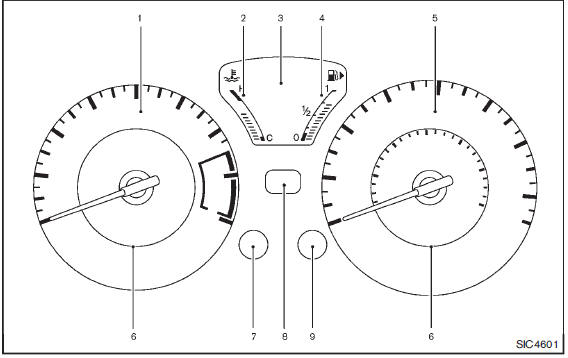
1. Tachometer
2. Engine coolant temperature gauge
3. Vehicle information display
— Odometer/twin trip odometer
— Trip computer
— Torque vectoring AWD (AWD model)
— Outside air temperature
4. Fuel gauge
5. Speedometer
6. Warning/indicator lights
7. Instrument brightness control knob
8. Continuously Variable Transmission (CVT) position indicator
9. RESET switch for trip odometer/Trip computer mode switch
: if so equipped
The needle indicators may move slightly after the ignition switch is placed in the OFF or LOCK position. This is not a malfunction.
CAUTION
• For cleaning, use a soft cloth, dampened with water. Never use a rough cloth, alcohol, benzine, thinner or any kind of solvent or paper towel with a chemical cleaning agent.
They will scratch or cause discoloration to the lens.
• Do not spray any liquid such as water on the meter lens. Spraying liquid may cause the system to malfunction.
- Speedometer and odometer
- Tachometer
- Engine coolant temperature gauge
- Fuel gauge
- Vehicle information display
- Outside air temperature
- Continuously Variable Transmission (CVT) position indicator (if so equipped)
- Trip computer
 Instrument panel
1. Meters and gauges
2. Center ventilator
3. Audio system or Navigation system
— Clock
4. Hazard warning flasher switch
5. Integrated Control System
— Drive mode
— Heater and air condit ...
 Speedometer and odometer
Speedometer
The speedometer indicates vehicle speed in miles per hour (MPH) and kilometers
per hour (km/h).
Odometer/twin trip odometer
The odometer 1 /twin trip odometer 2 are displayed when ...
Other materials:
ECU diagnosis information
4WD control module
Reference Value
VALUES ON THE DIAGNOSIS TOOL
TERMINAL LAYOUT
PHYSICAL VALUES
*: The values are changed by throttle opening and engine speed.
CAUTION:
When using circuit tester to measure voltage for inspection, be sure not to
extend forcibly any connector
t ...
Power supply and ground circuit
PTC HEATER CONTROL UNIT : Diagnosis Procedure
1.CHECK FUSE
1. Turn ignition switch OFF.
2. Check 10A fuses (No. 3 and 7).
NOTE:
Refer to PG-23, "Fuse and Fusible Link Arrangement".
Is the inspection result normal?
YES >> GO TO 2.
NO >> Replace the blown fuse after ...
Precaution Necessary for Steering Wheel Rotation after Battery Disconnect
NOTE:
• Before removing and installing any control units, first turn the ignition
switch to the LOCK position, then disconnect
both battery cables.
• After finishing work, confirm that all control unit connectors are connected
properly, then re-connect both
battery cables.
• Always us ...
