Nissan Juke Service and Repair Manual : Unlock sensor
Component Function Check
1.CHECK FUNCTION
1. Select “INTELLIGENT KEY” of “BCM” using CONSULT-III.
2. Select “UNLK SEN -DR” in “DATA MONITOR” mode.
3. Check that the function operates normally according to the following conditions.
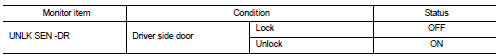
Is the inspection result normal? YES >> Unlock sensor is OK.
NO >> Refer to DLK-270, "Diagnosis Procedure".
Diagnosis Procedure
1.CHECK BCM OUTPUT SIGNAL
1. Turn ignition switch OFF.
2. Disconnect front door lock assembly (driver side) connector.
3. Check signal between front door lock assembly (driver side) harness connector and ground using oscilloscope.
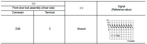
Is the inspection result normal? YES >> GO TO 3.
NO >> GO TO 2.
2.CHECK UNLOCK SENSOR CIRCUIT
1. Disconnect BCM connector.
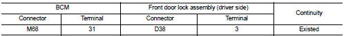
2. Check continuity between BCM harness connector and front door lock assembly (driver side) harness connecto
3. Check continuity between BCM harness connector and ground.
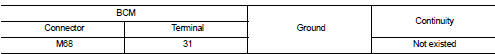
Is the inspection result normal? YES >> Replace BCM. Refer to BCS-93, "Removal and Installation".
NO >> Repair or replace harness.
3.CHECK UNLOCK SENSOR GROUND CIRCUIT
Check continuity between front door lock assembly (driver side) harness connector and ground.
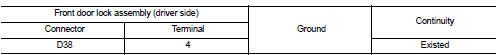
Is the inspection result normal? YES >> GO TO 4.
NO >> Repair or replace harness.
4.CHECK UNLOCK SENSOR
Refer to DLK-271, "Component Inspection".
Is the inspection result normal? YES >> GO TO 5.
NO >> Replace front door lock assembly (driver side).
5.CHECK INTERMITTENT INCIDENT
Refer to GI-42, "Intermittent Incident".
>> INSPECTION END
Component Inspection
1.CHECK UNLOCK SENSOR
1. Turn ignition switch OFF.
2. Disconnect front door lock assembly (driver side) connector.
3. Check continuity between front door lock assembly (driver side) terminals.
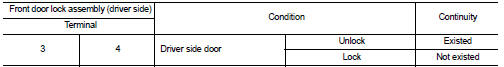
Is the inspection result normal? YES >> INSPECTION END
NO >> Replace front lock assembly (driver side).
 Shift P warning lamp
Component Function Check
1.CHECK FUNCTION
1. Select “INTELLIGENT KEY” of “BCM” using CONSULT-III.
2. Select “LCD” in “ACTIVE TEST” mode.
3. Check that the function operates normall ...

Other materials:
Back door opener system
System Diagram
System Description
BACK DOOR OPENER OPERATION
When back door opener switch is pressed, BCM operates back door opener
actuator.
NOTE:
Back door opener actuator is not for locking the back door. The function is only
to open the back door.
OPERATION CONDITION
If the foll ...
Interior room lamp control system
Wiring Diagram
For connector terminal arrangements, harness layouts, and alphabets in a
(option abbreviation: if not
described in wiring diagram), refer to GI-12, "Connector Information/Explanation
of Option Abbreviation".
...
Forward-facing child restraint installation using LATCH
Refer to all Warnings and Cautions in the “Child safety” and “Child restraints”
sections before installing a child restraint.
Follow these steps to install a forward-facing child restraint using the LATCH
system:
1. Position the child restraint on the seat.
Always follow the child res ...
