Nissan Juke Service and Repair Manual : P1805 brake switch
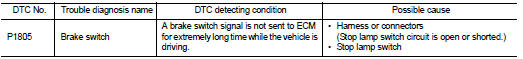
DTC Logic
DTC DETECTION LOGIC
DTC CONFIRMATION PROCEDURE
1.PERFORM DTC CONFIRMATION PROCEDURE
1. Turn ignition switch ON.
2. Fully depress the brake pedal for at least 5 seconds.
3. Erase DTC.
4. Check 1st trip DTC.
Is 1st trip DTC detected? YES >> Go to EC-734, "Diagnosis Procedure".
NO >> INSPECTION END
Diagnosis Procedure
1.CHECK STOP LAMP SWITCH CIRCUIT
1. Turn ignition switch OFF.
2. Check the stop lamp when depressing and releasing the brake pedal.
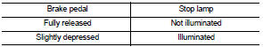
Is the inspection result normal? YES >> GO TO 4.
NO >> GO TO 2.
2.CHECK STOP LAMP SWITCH POWER SUPPLY CIRCUIT
1. Turn ignition switch OFF.
2. Disconnect stop lamp switch harness connector.
3. Check the voltage between stop lamp switch harness connector and ground.
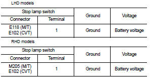
Is the inspection result normal? YES >> GO TO 4.
NO >> GO TO 3.
3.DETECT MALFUNCTIONING PART
Check the following.
• Harness connectors E105, M77, M84, M201 (RHD models with M/T)
• 10 A fuse (No. 38)
• Harness for open or short between stop lamp switch and battery
>> Repair open circuit or short to ground or short to power in harness or connectors.
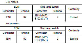
4.CHECK STOP LAMP SWITCH INPUT SIGNAL CIRCUIT FOR OPEN AND SHORT
1. Disconnect stop lamp switch harness connector.
2. Disconnect ECM harness connector.
3. Check the continuity between ECM harness connector and stop lamp switch harness connector.
4. Also check harness for short to ground and short to power.
Is the inspection result normal? YES >> GO TO 5.
NO >> Repair open circuit or short to ground or short to power in harness or connectors.
5.CHECK STOP LAMP SWITCH
Refer to EC-735, "Component Inspection".
Is the inspection result normal? YES >> GO TO 6.
NO >> Replace brake pedal assembly.
6.CHECK INTERMITTENT INCIDENT
Refer to GI-42, "Intermittent Incident".
>> INSPECTION END
Component Inspection
1.CHECK STOP LAMP SWITCH-I
1. Turn ignition switch OFF.
2. Disconnect stop lamp switch harness connector.
3. Check the continuity between stop lamp switch terminals under the following conditions.
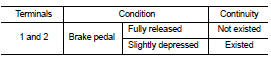
Is the inspection result normal? YES >> INSPECTION END
NO >> GO TO 2.
2.CHECK STOP LAMP SWITCH-II
1. Adjust stop lamp switch installation. Refer to BR-22, "Inspection and Adjustment" (LHD models), BR-90, "Inspection and Adjustment" (RHD models).
2. Check the continuity between stop lamp switch terminals under the following conditions.
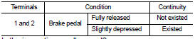
Is the inspection result normal? YES >> INSPECTION END
NO >> Replace brake pedal assembly. Refer to BR-89, "Removal and Installation".
 P1715 input speed sensor
Description
ECM receives input speed sensor signal from TCM via the CAN communication
line. ECM uses this signal for
engine control.
DTC Logic
DTC DETECTION LOGIC
NOTE:
• If DTC P1715 is dis ...
 P2100, P2103 throttle control motor relay
DTC Logic
DTC DETECTION LOGIC
DTC CONFIRMATION PROCEDURE
1.PRECONDITIONING
If DTC Confirmation Procedure has been previously conducted, always turn
ignition switch OFF and wait at
least 10 se ...
Other materials:
Exterior lighting system symptoms
Without daytime running light system
WITHOUT DAYTIME RUNNING LIGHT SYSTEM : Symptom Table
CAUTION:
Perform the self-diagnosis with CONSULT-III before the symptom diagnosis.
Perform the trouble diagnosis
if any DTC is detected.
With daytime running light system
WITH DAYTIME RUNNING LIGHT ...
Precaution
Precaution for Supplemental Restraint System (SRS) "AIR BAG" and "SEAT
BELT
PRE-TENSIONER"
The Supplemental Restraint System such as “AIR BAG” and “SEAT BELT PRE-TENSIONER”,
used along
with a front seat belt, helps to reduce the risk or severity of injury to the
...
Service data and specifications (SDS)
DRIVE BELT (MR16DDT)
DRIVE BELT (MR16DDT) : Drive Belt
DRIVE BELT
DRIVE BELT (HR16DE)
DRIVE BELT (HR16DE) : Drive Belt
DRIVE BELT
Belt Deflection
*: When engine is cold.
Belt Tension and Frequency
*: When engine is cold.
DRIVE BELT (K9K)
DRIVE BELT (K9K) : Drive Belt
DRIVE BELT ...
