Nissan Juke Service and Repair Manual : P1715 input speed sensor
Description
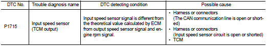
ECM receives input speed sensor signal from TCM via the CAN communication line. ECM uses this signal for engine control.
DTC Logic
DTC DETECTION LOGIC
NOTE
:
ŌĆó If DTC P1715 is displayed with DTC UXXXX, first perform the trouble diagnosis
for DTC UXXXX.
ŌĆó If DTC P1715 is displayed with DTC P0335, first perform the trouble diagnosis for DTC P0335. Refer to EC-656, "DTC Logic".
ŌĆó If DTC P1715 is displayed with DTC P0340, first perform the trouble diagnosis for DTC P0340. Refer to EC-660, "DTC Logic".
ŌĆó If DTC P1715 is displayed with DTC P0605, first perform the trouble diagnosis for DTC P0605. Refer to EC-683, "DTC Logic".
DTC CONFIRMATION PROCEDURE
1.PRECONDITIONING
If DTC Confirmation Procedure has been previously conducted, always turn ignition switch OFF and wait at least 10 seconds before conducting the next test.
>> GO TO 2.
2.PERFORM DTC CONFIRMATION PROCEDURE
1. Start engine and drive the vehicle at more than 50 km/h (31 MPH) for at least 5 seconds.
CAUTION:
Always drive vehicle at a safe speed.
2. Check 1st trip DTC.
Is 1st trip DTC detected? YES >> Go to EC-733, "Diagnosis Procedure".
NO >> INSPECTION END
Diagnosis Procedure
1.CHECK DTC WITH TCM
Check DTC with TCM. Refer to TM-171, "DTC Index".
Is the inspection result normal? YES >> GO TO 2.
NO >> Perform trouble shooting relevant to DTC indicated.
2.REPLACE TCM
Replace TCM. Refer to TM-280, "Exploded View".
>> INSPECTION END
 P1652 starter motor system COMM
Description
ECM controls ON/OFF state of the starter relay, according to the engine and
vehicle condition. Models with no
Intelligent Key System transmit a control signal directly to IPDM E/R. On ...
 P1805 brake switch
DTC Logic
DTC DETECTION LOGIC
DTC CONFIRMATION PROCEDURE
1.PERFORM DTC CONFIRMATION PROCEDURE
1. Turn ignition switch ON.
2. Fully depress the brake pedal for at least 5 seconds.
3. Erase DTC. ...
Other materials:
Camshaft
*: Total indicator readin
VALVE LIFTER
VALVE CLEARANCE
*: Approximately 80┬░C (176┬░F)
AVAILABLE VALVE LIFTER
...
P0075 IVT control solenoid valve
DTC Logic
DTC DETECTION LOGIC
DTC CONFIRMATION PROCEDURE
1.PRECONDITIONING
If DTC Confirmation Procedure has been previously conducted, always perform
the following procedure
before conducting the next test.
1. Turn ignition switch OFF and wait at least 10 seconds.
2. Turn ignition swit ...
Anti-hijack function does not operate
Diagnosis Procedure
1.CHECK ŌĆ£DOOR LOCKŌĆōUNLOCK SETŌĆØ SETTING IN ŌĆ£WORK SUPPORTŌĆØ
1. Select ŌĆ£DOOR LOCKŌĆØ of ŌĆ£BCMŌĆØ using CONSULT-III.
2. Select ŌĆ£DOOR LOCK-UNLOCK SETŌĆØ in ŌĆ£WORK SUPPORTŌĆØ mode.
3. Check ŌĆ£DOOR LOCK-UNLOCK SETŌĆØ in ŌĆ£WORK SUPPORTŌĆØ
Refer to DLK-41, "DOOR ...
