Nissan Juke Service and Repair Manual : P2100, P2103 throttle control motor relay
DTC Logic
DTC DETECTION LOGIC
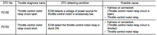
DTC CONFIRMATION PROCEDURE
1.PRECONDITIONING
If DTC Confirmation Procedure has been previously conducted, always turn ignition switch OFF and wait at least 10 seconds before conducting the next test.
TESTING CONDITION:
Before performing the following procedure, confirm that battery voltage is more
than 8 V.
Witch DTC is detected? P2100 >> GO TO 2.
P2103 >> GO TO 3.
2.PERFORM DTC CONFIRMATION PROCEDURE FOR DTC P2100
1. Turn ignition switch ON and wait at least 2 seconds.
2. Start engine and let it idle for 5 seconds.
3. Check DTC.
Is DTC detected? YES >> Go to EC-737, "Diagnosis Procedure".
NO >> INSPECTION END
3.PERFORM DTC CONFIRMATION PROCEDURE FOR DTC P2103
1. Turn ignition switch ON and wait at least 1 second.
2. Check DTC.
Is DTC detected? YES >> Go to EC-737, "Diagnosis Procedure".
NO >> INSPECTION END
Diagnosis Procedure
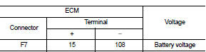
1.CHECK THROTTLE CONTROL MOTOR RELAY POWER SUPPLY CIRCUIT-I
1. Turn ignition switch OFF.
2. Check voltage between ECM harness connector and ground.
Is the inspection result normal? YES >> GO TO 5.
NO >> GO TO 2.
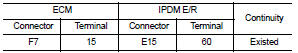
2.CHECK THROTTLE CONTROL MOTOR RELAY INPUT SIGNAL CIRCUIT-I
1. Disconnect ECM harness connector.
2. Disconnect IPDM E/R harness connector E15.
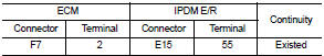
3. Check the continuity between ECM harness connector and IPDM E/R harness connector.
4. Also check harness for short to ground and short to power.
Is the inspection result normal? YES >> GO TO 4.
NO >> GO TO 3.
3.DETECT MALFUNCTIONING PART
Check the following.
• Harness connectors E8, F1 • IPDM E/R connector E15 • Harness for open or short between IPDM E/R and ECM
>> Repair open circuit or short to ground or short to power in harness or connectors.
4.CHECK FUSE
1. Disconnect 15 A fuse (No. 64) from IPDM E/R.
2. Check 15 A fuse for blown.
Is the inspection result normal? YES >> GO TO 8.
NO >> Replace 15 A fuse.
5.CHECK THROTTLE CONTROL MOTOR RELAY INPUT SIGNAL CIRCUIT-I
1. Check voltage between ECM harness connector and ground under the following conditions.
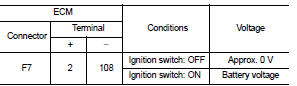
Is the inspection result normal? YES >> GO TO 8.
NO >> GO TO 6.
6.CHECK THROTTLE CONTROL MOTOR RELAY INPUT SIGNAL CIRCUIT-II
1. Turn ignition switch OFF.
2. Disconnect ECM harness connector.
3. Disconnect IPDM E/R harness connector E15.
4. Check the continuity between ECM harness connector and IPDM E/R harness connector.
5. Also check harness for short to ground and short to power.
Is the inspection result normal? YES >> GO TO 8.
NO >> GO TO 7.
7.DETECT MALFUNCTIONING PART
Check the following.
• Harness connectors E8, F1 • IPDM E/R connector E15 • Harness for open or short between IPDM E/R and ECM
>> Repair open circuit or short to ground or short to power in harness or connectors.
8.CHECK INTERMITTENT INCIDENT
Refer to GI-42, "Intermittent Incident".
Is the inspection result normal? YES >> Replace IPDM E/R.
NO >> Repair or replace harness or connectors.
 P1805 brake switch
DTC Logic
DTC DETECTION LOGIC
DTC CONFIRMATION PROCEDURE
1.PERFORM DTC CONFIRMATION PROCEDURE
1. Turn ignition switch ON.
2. Fully depress the brake pedal for at least 5 seconds.
3. Erase DTC. ...
 P2101 electric throttle control function
DTC Logic
DTC DETECTION LOGIC
NOTE:
• If DTC P2101 is displayed with DTC P2100, first perform the trouble diagnosis
for DTC P2100. Refer
to EC-737, "DTC Logic".
• If DTC P2101 is ...
Other materials:
Unit removal and installation
TRANSMISSION ASSEMBLY
Exploded View
1. Transaxle assembly
A: : For the tightening torque, refer to TM-508, "Removal and Installation".
Removal and Installation
REMOVAL
WARNING:
Never open the radiator cap or drain plug when the engine is hot. Hot liquid may
spray out, causing
s ...
S mode indicator
Component Function Check
1.CHECK S MODE INDICATOR FUNCTION
Check S mode indicator turns ON for approx. 2 seconds when ignition switch
turns ON.
Is the inspection results normal?
YES >> INSPECTION END
NO >> Go to TM-469, "Diagnosis Procedure".
Diagnosis Procedure
1.CH ...
Precautions when starting and driving
WARNING
Do not leave young children or adults who would normally require the physical support of others unattended or alone in your vehicle. Pets should not be left alone inside the cabin either. They could accidentally injure themselves or others through the inadvertent operation of ...
