Nissan Juke Service and Repair Manual : P2101 electric throttle control function
DTC Logic
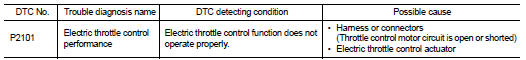
DTC DETECTION LOGIC
NOTE
:
• If DTC P2101 is displayed with DTC P2100, first perform the trouble diagnosis
for DTC P2100. Refer
to EC-737, "DTC Logic".
• If DTC P2101 is displayed with DTC P2119, first perform the trouble diagnosis for DTC P2119. Refer to EC-746, "DTC Logic".
DTC CONFIRMATION PROCEDURE
1.PRECONDITIONING
If DTC Confirmation Procedure has been previously conducted, always turn ignition switch OFF and wait at least 10 seconds before conducting the next test.
TESTING CONDITION:
Before performing the following procedure, confirm that battery voltage is more
than 11 V when
engine is running.
>> GO TO 2.
2.PERFORM DTC CONFIRMATION PROCEDURE
1. Turn ignition switch ON and wait at least 2 seconds.
2. Start engine and let it idle for 5 seconds.
3. Check DTC.
Is DTC detected? YES >> Go to EC-740, "Diagnosis Procedure".
NO >> INSPECTION END
Diagnosis Procedure
1.CHECK GROUND CONNECTION
1. Turn ignition switch OFF.
2. Check ground connection E21 and E38. Refer to Ground Inspection in GI-44, "Circuit Inspection".
Is the inspection result normal? YES >> GO TO 2.
NO >> Repair or replace ground connection.
2.CHECK THROTTLE CONTROL MOTOR RELAY INPUT SIGNAL CIRCUIT
1. Turn ignition switch ON.
2. Check the voltage between ECM harness connector and ground.
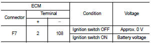
Is the inspection result normal? YES >> GO TO 10.
NO >> GO TO 3.
3.CHECK THROTTLE CONTROL MOTOR RELAY POWER SUPPLY CIRCUIT-I
1. Turn ignition switch OFF.
2. Check voltage between ECM harness connector and ground.
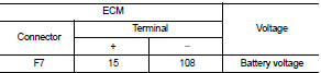
Is the inspection result normal? YES >> GO TO 7.
NO >> GO TO 4.
4.CHECK THROTTLE CONTROL MOTOR RELAY POWER SUPPLY CIRCUIT-II
1. Disconnect ECM harness connector.
2. Disconnect IPDM E/R harness connector E15.
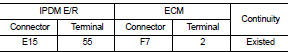
3. Check the continuity between ECM harness connector and IPDM E/R harness connector.
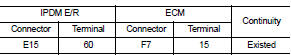
4. Also check harness for short to ground and short to power.
Is the inspection result normal? YES >> GO TO 6.
NO >> GO TO 5.
5.DETECT MALFUNCTIONING PART
Check the following.
• Harness connectors E8, F1 • IPDM E/R connector E15 • Harness for open or short between IPDM E/R and ECM
>> Repair open circuit or short to ground or short to power in harness or connectors.
6.CHECK FUSE
1. Disconnect 15 A fuse (No. 64) from IPDM E/R.
2. Check 15 A fuse for blown.
Is the inspection result normal? YES >> GO TO 9.
NO >> Replace 15 A fuse.
7.CHECK THROTTLE CONTROL MOTOR RELAY POWER SUPPLY CIRCUIT-III
1. Disconnect ECM harness connector.
2. Disconnect IPDM E/R harness connector E15.
3. Check the continuity between ECM harness connector and IPDM E/R harness connector.
4. Also check harness for short to ground and short to power.
Is the inspection result normal? YES >> GO TO 9.
NO >> GO TO 8.
8.DETECT MALFUNCTIONING PART
Check the following.
• Harness connectors E8, F1 • IPDM E/R connector E15 • Harness for open or short between IPDM E/R and ECM
>> Repair open circuit or short to ground or short to power in harness or connectors.
9.CHECK INTERMITTENT INCIDENT
Refer to GI-42, "Intermittent Incident".
Is the inspection result normal? YES >> Replace IPDM E/R.
NO >> Repair or replace harness or connectors.
10.CHECK THROTTLE CONTROL MOTOR OUTPUT SIGNAL CIRCUIT FOR OPEN OR SHORT
1. Turn ignition switch OFF.
2. Disconnect electric throttle control actuator harness connector.
3. Disconnect ECM harness connector.
4. Check the continuity between electric throttle control actuator harness connector and ECM harness connector.
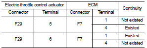
5. Also check harness for short to ground and short to power.
Is the inspection result normal? YES >> GO TO 11.
NO >> Repair or replace harness or connectors.
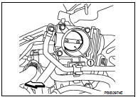
11.CHECK ELECTRIC THROTTLE CONTROL ACTUATOR VISUALLY
1. Remove the intake air duct.
2. Check if foreign matter is caught between the throttle valve (1) and the housing.
-  : Vehicle front
Is the inspection result normal? YES >> GO TO 12.
NO >> Remove the foreign matter and clean the electric throttle control actuator inside.
12.CHECK THROTTLE CONTROL MOTOR
Refer to EC-743, "Component Inspection".
Is the inspection result normal? YES >> GO TO 13.
NO >> GO TO 14.
13.CHECK INTERMITTENT INCIDENT
Refer to GI-42, "Intermittent Incident".
Is the inspection result normal?
YES >> GO TO 14.
NO >> Repair or replace harness or connectors.
14.REPLACE ELECTRIC THROTTLE CONTROL ACTUATOR
Replace malfunction electric throttle control actuator. Refer to EM-163, "Exploded View".
>> INSPECTION END
Component Inspection
1.CHECK THROTTLE CONTROL MOTOR
1. Disconnect electric throttle control actuator harness connector.
2. Check resistance between electric throttle control actuator terminals as follows.
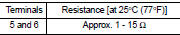
Is the inspection result normal?
YES >> INSPECTION END
NO >> GO TO 2.
2.REPLACE ELECTRIC THROTTLE CONTROL ACTUATOR
Replace electric throttle control actuator. Refer to EM-163, "Exploded View".
>> INSPECTION END
 P2100, P2103 throttle control motor relay
DTC Logic
DTC DETECTION LOGIC
DTC CONFIRMATION PROCEDURE
1.PRECONDITIONING
If DTC Confirmation Procedure has been previously conducted, always turn
ignition switch OFF and wait at
least 10 se ...
 P2118 throttle control motor
DTC Logic
DTC DETECTION LOGIC
DTC CONFIRMATION PROCEDURE
1.PRECONDITIONING
If DTC Confirmation Procedure has been previously conducted, always turn
ignition switch OFF and wait at
least 10 se ...
Other materials:
Power generation voltage variable control system operation
inspection
Inspection Procedure
CAUTION:
When performing this inspection, always use a charged battery that has completed
the battery inspection.
(When the charging rate of the battery is low, the response speed of the voltage
change will
become slow. This can cause an incorrect inspection.)
1.CHECK ...
Intake valve timing control
Intake valve timing control : System Diagram
Intake valve timing control : System Description
INPUT/OUTPUT SIGNAL CHART
SYSTEM DESCRIPTION
This mechanism hydraulically controls cam phases continuously with the fixed
operating angle of the intakevalve.
The ECM receives signals such as ...
Push-button ignition switch positions
LOCK (Normal parking position)
The ignition switch can only be locked in this position.
The ignition switch will be unlocked when it is pushed to the ACC position while
carrying the Intelligent Key.
ACC (Accessories)
This position activates electrical accessories such as the radio, when the en ...
