Nissan Juke Service and Repair Manual : P0045, P0047, P0048 TC boost control solenoid valve
DTC Logic
DTC DETECTION LOGIC
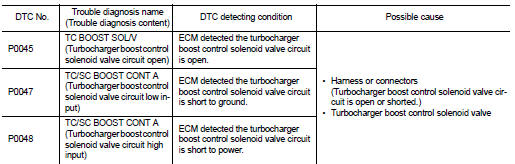
DTC CONFIRMATION PROCEDURE
1.PRECONDITIONING
If DTC Confirmation Procedure has been previously conducted, always perform the following procedure before conducting the next test.
1. Turn ignition switch OFF and wait at least 10 seconds.
2. Turn ignition switch ON.
3. Turn ignition switch OFF and wait at least 10 seconds.
>> GO TO 2.
2.PERFORM DTC CONFIRMATION PROCEDURE
1. Turn ignition switch ON and wait at least 5 seconds.
2. Check 1st trip DTC.
Is 1st trip DTC detected? YES >> Proceed to EC-174, "Diagnosis Procedure".
NO >> INSPECTION END
Diagnosis Procedure
1.CHECK TURBOCHARGER BOOST CONTROL SOLENOID VALVE POWER SUPPLY
1. Turn ignition switch OFF.
2. Disconnect turbocharger boost control solenoid valve harness connector.
3. Turn ignition switch ON.
4. Check the voltage between turbocharger boost control solenoid valve harness connector and ground.
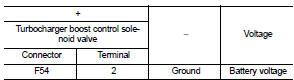
Is the inspection result normal? YES >> GO TO 3.
NO >> GO TO 2.
2.CHECK TURBOCHARGER BOOST CONTROL SOLENOID VALVE POWER SUPPLY CIRC
1. Turn ignition switch OFF.
2. Disconnect IPDM E/R harness connector.
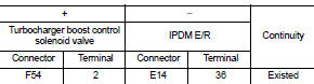
3. Check the continuity between turbocharger boost control solenoid valve harness connector and IPDM E/R harness connector.
4. Also check harness for short to ground.
Is the inspection result normal? YES >> Perform the trouble diagnosis for power supply circuit.
NO >> Repair or replace error-detected parts.
3.CHECK TURBOCHARGER BOOST CONTROL SOLENOID VALVE GROUND CIRCUIT
1. Turn ignition switch OFF.
2. Disconnect ECM harness connector.
3. Check the continuity between turbocharger boost control solenoid valve harness connector and ECM harness connector.

4. Also check harness for short to ground and to power.
Is the inspection result normal? YES >> GO TO 4.
NO >> Repair or replace error-detected parts.
4.CHECK TURBOCHARGER BOOST CONTROL SOLENOID VALVE
Check the turbocharger boost control solenoid valve. Refer to EC-175, "Component Inspection".
Is the inspection result normal? YES >> Check intermittent incident. Refer to GI-42, "Intermittent Incident".
NO >> Replace turbocharger boost control solenoid valve. Refer to EM-36, "Exploded View".
Component Inspection
1.CHECK TURBOCHARGER BOOST CONTROL SOLENOID VALVE
1. Turn ignition switch OFF 2. Disconnect turbocharger boost control solenoid valve harness connector.
3. Disconnect hoses connected to turbocharger boost control solenoid valve.
4. Check air passage continuity of turbocharger boost control solenoid valve as per the following conditions.
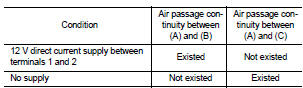
Is the inspection result normal? YES >> INSPECTION END NO >> Replace turbocharger boost control solenoid valve. Refer to EM-36, "Exploded View".
 P0037, P0038 HO2S2 heater
DTC Logic
DTC DETECTION LOGIC
DTC CONFIRMATION PROCEDURE
1.PRECONDITIONING
If DTC Confirmation Procedure has been previously conducted, always perform
the following procedure before conducting ...
 P0075 IVT control solenoid valve
DTC Logic
DTC DETECTION LOGIC
DTC CONFIRMATION PROCEDURE
1.PRECONDITIONING
If DTC Confirmation Procedure has been previously conducted, always perform
the following procedure
before conductin ...
Other materials:
System
System Diagram
MODELS WITH USB CONNECTION FUNCTION
NOTE:
An antenna base integrated with radio antenna amp. is adopted.
MODELS WITHOUT USB CONNECTION FUNCTION
NOTE:
An antenna base integrated with radio antenna amp. is adopted.
System Description
AUDIO SYSTEM
Audio functions
AUDIO ...
Front drive shaft boot
Exploded View
LEFT SIDE
1. Circular clip
2. Dust shield
3. Housing assembly
4. Boot band
5. Boot
6. Damper band
7. Dynamic damper
8. Circular clip
9. Joint sub-assembly
: Wheel side
: Fill NISSAN Genuine grease or
equivalent.
: Always replace after every
disassembly.
RIGHT ...
The braking distance is long
Description
Brake stopping distance is long when ABS function is operated.
Diagnosis Procedure
CAUTION:
Brake stopping distance on slippery road like rough road, gravel road or snowy
road may become
longer when ABS is operated than when ABS is not operated.
1.CHECK BRAKING FORCE
Check bra ...
