Nissan Juke Service and Repair Manual : Engine protection control at low engine oil pressure
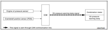
Engine protection control at low engine oil pressure : System Diagram
Engine protection control at low engine oil pressure : System Description
INPUT/OUTPUT SIGNAL CHART

SYSTEM DESCRIPTION
• The engine protection control at low engine oil pressure warns the driver of a decrease in engine oil pressure by the oil pressure warning lamp a before the engine becomes damaged.
• When detecting a decrease in engine oil pressure at an engine speed less than 1,000 rpm, ECM transmits an oil pressure warning lamp signal to the combination meter.The combination meter turns ON the oil pressure warning lamp, according to the signal.
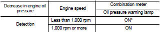
*: When detecting a normal engine oil pressure, ECM turns OFF the oil pressure warning lamp.
 Turbocharger boost control
Turbocharger boost control : SystemDiagram
Turbocharger boost control : System Description
INPUT/OUTPUT SIGNAL CHART
SYSTEM DESCRIPTION
Depending on driving conditions, the ECM performs ON/OFF ...
 Air conditioning cut control
Air conditioning cut control : System Diagram
Air conditioning cut control : System Description
INPUT/OUTPUT SIGNAL CHART
*: ECM determines the start signal status by the signals of engine spe ...
Other materials:
ESP warning lamp
Component Function Check
1.CHECK ESP WARNING LAMP FUNCTION
Check that ESP warning lamp in combination meter turns ON for approx. 1
second after ignition switch is
turned ON.
CAUTION:
Never start engine.
Is the inspection result normal?
YES >> INSPECTION END
NO >> Proceed to d ...
Check anti-pinch function
Description
If any of the following operations are performed, the initialization is
necessary for normal operation of antipinch
function.
• Disconnection and connection of battery cable from negative terminal.
• When power window main switch replaced.
• Electric power supply to power ...
Air cleaner and air duct
Exploded View
1. Hose clamp
2. PCV hose
3. Hose clamp
4. Air cleaner filter
5. Air cleaner filter case
6. Grommet
7. Inlet air duct (lower)
8. Grommet
9. Inlet air duct (upper)
10. Bracket
11. Air cleaner case
12. O-ring
13. Mass air flow sensor
14. Air duct
A. To electric ...
