Nissan Juke Service and Repair Manual : Turbocharger boost control
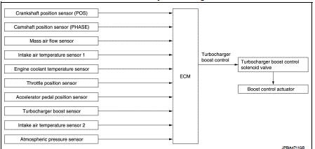
Turbocharger boost control : SystemDiagram
Turbocharger boost control : System Description
INPUT/OUTPUT SIGNAL CHART
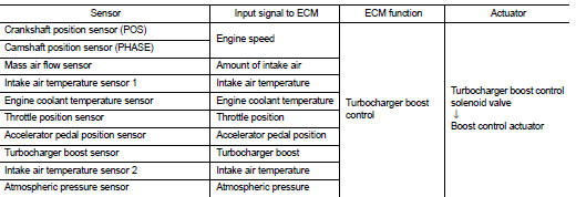
SYSTEM DESCRIPTION
Depending on driving conditions, the ECM performs ON/OFF duty control of the turbocharger boost control solenoid valve and controls the boost by adjusting the pressure to the diaphragm of the boost control actuator.
When driving conditions demand an increase in boost, the ECM prolongs the ON time of the turbocharger boost control solenoid valve and moves the boost control valve towards the closing direction by reducing the pressure in the diaphragm of the boost control actuator. The emission gas to the turbine wheel is then increased. When driving conditions demand a decrease in boost, the ECM shortens the ON time of the turbocharger boost control solenoid valve and moves the boost control valve towards the opening position by increasing the pressure in the diaphragm of the boost control actuator. The emission bypassing to the turbine wheel is then increased. Thus, by performing the most optimal boost control, the ECM improves engine output and response.
NOTE
:
The boost varies depending on the vehicle and driving conditions.
BOOST CONTROL ACTUATOR LINE DRAWING
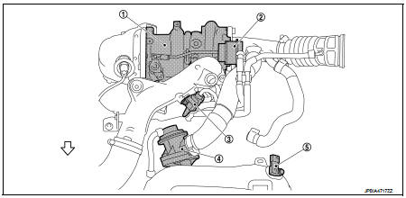
1. Turbocharger
2. Boost control actuator
3. Turbocharger boost control solenoid
valve
4. Recirculation valve
5. Turbocharger boost sensor
(with intake air temperature sensor 2)
 : Vehicle front
 Exhaust valve timing control
Exhaust valve timing control : System Diagram
Exhaust valve timing control: System Description
INPUT/OUTPUT SIGNAL CHART
SYSTEM DESCRIPTION
This mechanism hydraulically controls cam phases c ...
 Engine protection control at low engine oil pressure
Engine protection control at low engine oil pressure : System Diagram
Engine protection control at low engine oil pressure : System Description
INPUT/OUTPUT SIGNAL CHART
SYSTEM DESCRIPTION
†...
Other materials:
Rear door glass
Exploded View
1. Rear door panel
2. Sealing screen
3. Lower sash (front)
4. Rear door regulator assembly
5. Power window motor
6. Rear door glass
7. Lower sash (rear)
8. Rear door glass run
Removal and Installation
REMOVAL
1. Fully open rear door glass.
2. Remove rear door finishe ...
System
NISSAN dynamic control system
NISSAN DYNAMIC CONTROL SYSTEM : System Description
SYSTEM DIAGRAM
• *1: M/T models except for K9K engine models
• *2: CVT models
MULTI DISPLAY UNIT INPUT/OUTPUT SINGNAL
Output signal
SYSTEM DESCRIPTION
• The multi display unit receives necessary info ...
All defogger system dose not operate
Description
Rear window defogger and door mirror defogger do not operate when rear window
defogger switch operated.
Diagnosis Procedure
1.CHECK REAR WINDOW DEFOGGER SWITCH
Check rear window defogger switch.
Refer to DEF-26, "WITH AUTO A/C : Component Function Check" (With Auto A/C ...
