Nissan Juke Service and Repair Manual : Exhaust valve timing control
Exhaust valve timing control : System Diagram
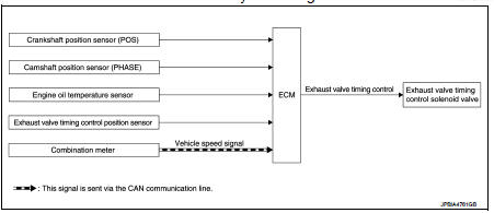
Exhaust valve timing control: System Description
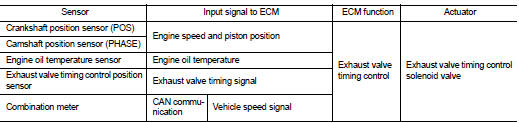
INPUT/OUTPUT SIGNAL CHART
SYSTEM DESCRIPTION
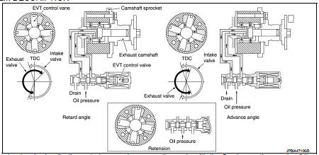
This mechanism hydraulically controls cam phases continuously with the fixed operating angle of the exhaust valve.
The ECM receives signals such as crankshaft position, camshaft position, engine speed, and engine oil temperature.
Then, the ECM sends ON/OFF pulse duty signals to the exhaust valve timing (EVT) control solenoid valve depending on driving status. This makes it possible to control the shut/open timing of the exhaust valve to increase engine torque and output in a range of high engine speed.
 Intake valve timing control
Intake valve timing control : System Diagram
Intake valve timing control : System Description
INPUT/OUTPUT SIGNAL CHART
SYSTEM DESCRIPTION
This mechanism hydraulically controls cam phases co ...
 Turbocharger boost control
Turbocharger boost control : SystemDiagram
Turbocharger boost control : System Description
INPUT/OUTPUT SIGNAL CHART
SYSTEM DESCRIPTION
Depending on driving conditions, the ECM performs ON/OFF ...
Other materials:
B1051, B1056 driver air bag module
DTC Logic
DTC DETECTION LOGIC
DTC CONFIRMATION PROCEDURE
1.CHECK SELF-DIAG RESULT
With CONSULT-III
1. Turn ignition switch ON.
2. Perform “Self Diagnostic Result” mode of “AIR BAG” using CONSULT-III.
Without CONSULT-III
1. Turn ignition switch ON.
2. Check the air bag warning la ...
Input shaft and gear
Exploded View
1. Input shaft front bearing
2. Input shaft
3. Snap ring
4. Input shaft rear bearing
5. Adapter plate
6. Bushing
7. 5th input gear
8. 5th-reverse baulk ring
9. Synchronizer lever
10. 5th-reverse synchronizer hub
11. 5th-reverse coupling sleeve
12. Retaining pin
1 ...
Life with an EV (scene guide)
This section serves as a practical guide to the most essential functions of your Nissan Leaf. To gain a deeper understanding of these capabilities and their operational nuances, please refer to the corresponding chapters in this manual, which provide comprehensive details regarding your vehicle's fe ...
