Nissan Juke Service and Repair Manual : Reference Value
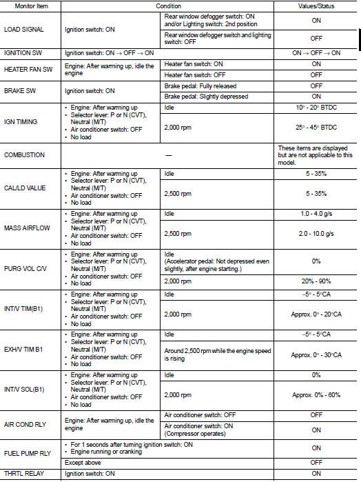
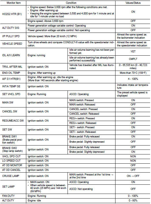
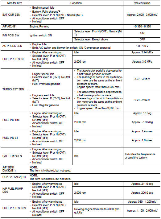
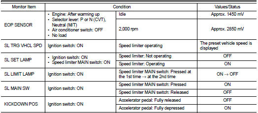
VALUES ON THE DIAGNOSIS TOOL
Remarks:
• Specification data are reference values.
• Specification data are output/input values which are detected or supplied by the ECM at the connector.
* Specification data may not be directly related to their components signals/values/operations.
I.e. Adjust ignition timing with a timing light before monitoring IGN TIMING, because the monitor may show the specification data in spite of the ignition timing not being adjusted to the specification data. this IGN TIMING monitors the data calculated by the ECM according to the signals input from the camshaft position sensor and other ignition timing related sensors.
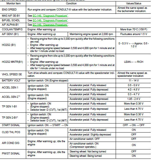
*1: Accelerator pedal position sensor 2 signal and throttle position sensor 2 signal are converted by ECM internally. Thus, they differ from ECM terminals voltage signal.
*2: Before measuring the terminal voltage, confirm that the battery is fully charged. Refer to PG-111, "How to Handle Battery".
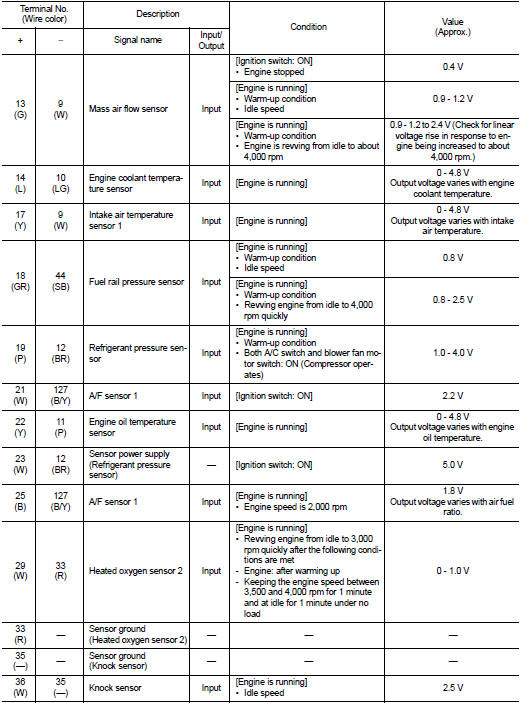
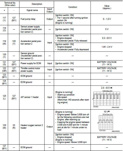
TERMINAL LAYOUT
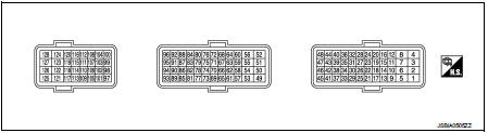
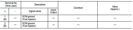
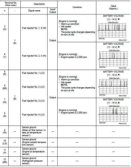
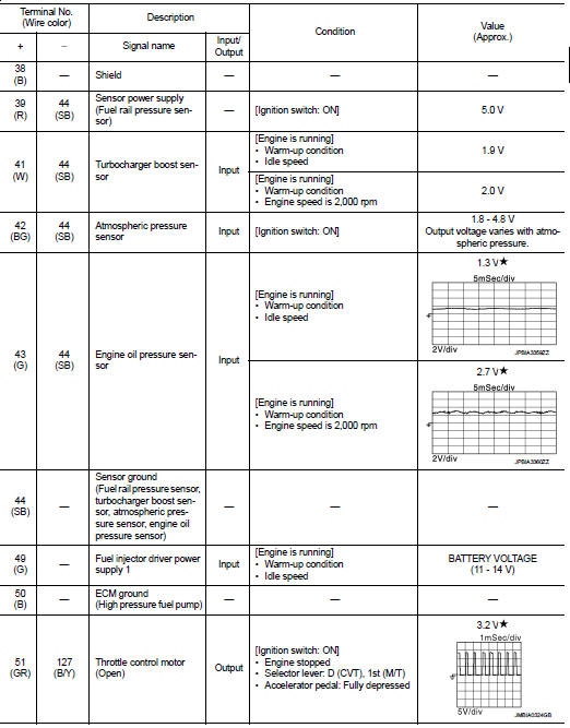
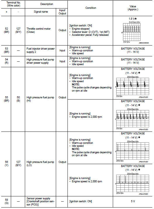
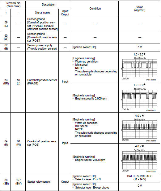
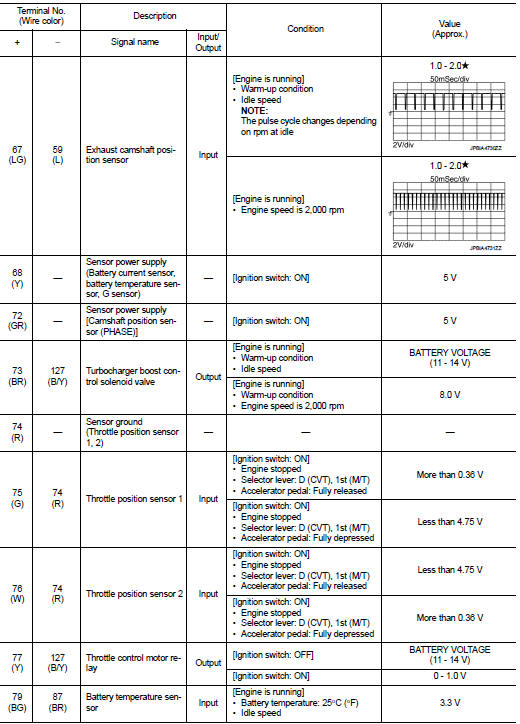
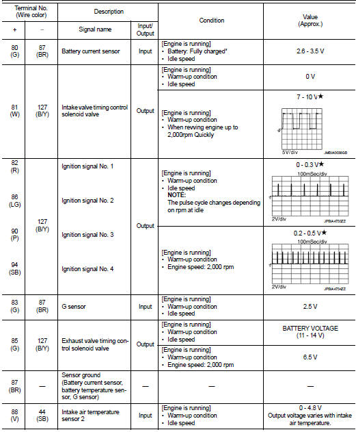
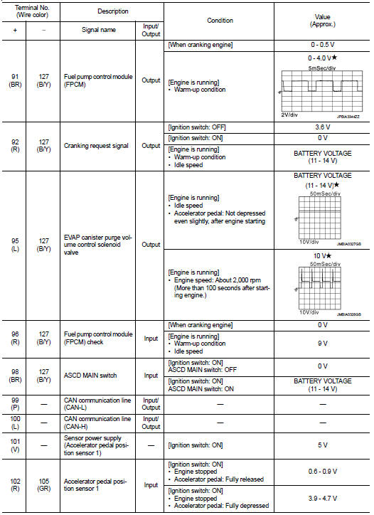
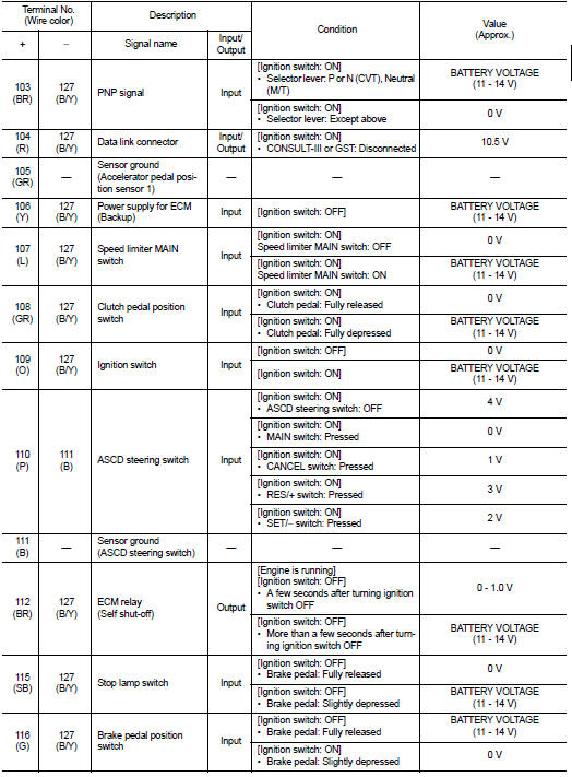
PHYSICAL VALUES
NOTE
:
• ECM is located in the engine room left side near battery.
• Connect a break-out box (EG17550000) and harness adapter (EG17550400) between the ECM and ECM harness connector.
- Use extreme care not to 2 pins at one time.
- Data is for comparison and may not be exact.
• Specification data are reference values and are measured between each terminal and ground.
• Pulse signal is measured by CONSULT-III.

 Fail Safe
NON DTC RELATED ITEM
DTC RELATED ITEM
...
Other materials:
Power window main switch
Reference Value
TERMINAL LAYOUT
PHYSICAL VALUES
POWER WINDOW MAIN SWITCH
Fail Safe
FAIL-SAFE CONTROL
Switches to fail-safe control when malfunction is detected in encoder signal
that detects up/down speed and
direction of door glass. Switches to fail-safe control when error beyond
r ...
B2110 shift position/clutch interlock switch
DTC Logic
DTC DETECTION LOGIC
NOTE:
If DTC B2110 is displayed with DTC U1000, first perform the trouble diagnosis
for DTC U1000. Refer to PCS-
30, "DTC Logic".
DTC CONFIRMATION PROCEDURE
1.PERFORM DTC CONFIRMATION PROCEDURE
1. Shift selector lever to the P position.
2. Turn ign ...
Heated seats (if so equipped)
WARNING
Do not use or allow occupants to use the seat heater if you or the occupants
cannot monitor elevated seat temperatures or have an inability to feel pain in body
parts that contact the seat. Use of the seat heater by such people could result
in serious injury.
CAUTION
• The battery ...
