Nissan Juke Service and Repair Manual : Operation
Autmatic speed control device (ASCD) : Switch Name and Function
SWITCHES AND INDICATORS
NOTE
:
Shared with speed limiter switch.
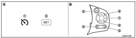
1. CRUISE indicator lamp
2. SET indicator lamp
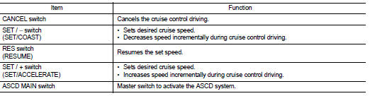
3. CANCEL switch
4. Speed limiter MAIN switch
5. ASCD MAIN switch
6. SET / − switch
(SET / COAST)
7. RES switch
(RESUME)
8. SET / + switch
(SET / ACCELERATE)
A. On the combination meter B. On the steering wheel
SET SPEED RANGE
ASCD system can be set the following vehicle speed.

SWITCH OPERATION
CANCEL CONDITION
• When any of following conditions exist, the cruise operation is canceled.
- CANCEL switch is pressed.
- ASCD MAIN switch is pressed. (Set speed is cleared.) - Speed limiter MAIN switch is pressed. (Set speed is cleared.) - More than two switches at ASCD steering switch are pressed at the same time.
- Brake pedal is depressed.
- Shift lever position is changed to neutral or reverse.
- Clutch pedal is depressed.
- TCS system is operated.
- Parking brake lever is operated.
• When the ECM detects any of the following conditions, the ECM cancels the cruise operation and informs the driver by blinking CRUISE indicator lamp.
- Malfunction for some self-diagnoses regarding ASCD system. SET indicator lamp is blinked quickly.
Speed limiter : Switch Name and Function
SWITCHES AND INDICATORS
NOTE
:
Shared with ASCD switch.
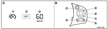
1. Speed limiter indicator lamp
2. SET indicator lamp
3. Set speed indicator
(On the information display)
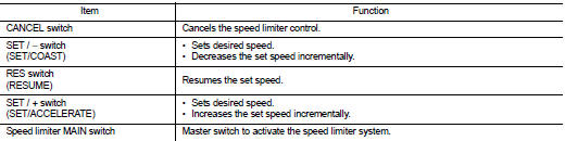
4. Speed limiter MAIN switch
5. Speed limiter MAIN switch
6. ASCD MAIN switch
7. SET / − switch
(SET / COAST)
8. RES switch
(RESUME)
9. SET / + switch
(SET / ACCELERATE)
A. On the combination meter B. On the steering wheel
SET SPEED RANGE
Speed limiter system can be set the following vehicle speed.

SWITCH OPERATION
CANCEL CONDITION
• When any of following conditions exist, speed limiter control is canceled.
- Speed limiter MAIN switch is pressed. (Set speed is cleared.) - ASCD MAIN switch is pressed. (Set speed is cleared.) - CANCEL switch is pressed.
• When accelerator pedal is fully depressed (Kickdown), speed limiter control is temporarily released. And driver can be driven above set speed (Set speed indicator is blinked).
• When the ECM detects any of the following conditions, the ECM cancels the speed limiter operation and informs the driver by blinking speed limiter indicator lamp and SET indicator lamp.
- Malfunction for some self-diagnosis regarding ASCD system.
 System
ENGINE CONTROL SYSTEM : System Diagram
1. Priming pump
2. Fuel filter
3. High pressure supply pump
4. High pressure supply pump (internal
transfer pump)
5. High pressure supply pump (volumet ...
 On board diagnostic (OBD) system
Diagnosis Description
The ECM controls the display on the instrument panel of certain information
relating to the operation of the
engine.
Four functions are involved here: The OBD malfunction ...
Other materials:
Component parts
CVT control system : Component Parts Location
1. Multi display unit (MDU)*
Refer to DMS-3, "Component Parts
Location".
2. Combination meter 3. S mode indicator
(On the combination meter)
4. Shift position indicator
(On the combination meter)
5. Malfunction indicator lamp (MIL)
( ...
B2581, B2582 intake sensor
DTC Logic
DTC DETECTION LOGIC
NOTE:
• If DTC is displayed along with DTC U1000, first perform the trouble diagnosis
for DTC U1000. Refer to HAC-
141, "DTC Logic".
• If DTC is displayed along with DTC U1010, first perform the trouble diagnosis
for DTC U1010. HAC-142,
"DTC ...
Tire Pressure Monitoring System (TPMS)
Your Nissan Leaf is equipped with a sophisticated Tire Pressure Monitoring System (TPMS) that continuously tracks the inflation pressure of all four tires. When the dedicated low tire pressure warning light illuminates on the instrument cluster, accompanied by the "Tire Pressure Low - Add Air" notif ...
