Nissan Juke Service and Repair Manual : System
ENGINE CONTROL SYSTEM : System Diagram
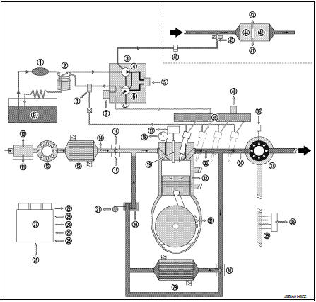
1. Priming pump
2. Fuel filter
3. High pressure supply pump
4. High pressure supply pump (internal
transfer pump)
5. High pressure supply pump (volumetric
control valve)
6. High pressure supply pump (high
pressure pump)
7. High pressure supply pump (pressure
control valve)
8. Fuel temperature sensor
9. Fuel tank
10. Mass air flow sensor
11. Intake air temperature sensor
12. Compressor
13. Charge air cooler
14. Turbocharger boost sensor
15. Electric throttle control actuator
16. Throttle position sensor
17. Glow relay
18. Camshaft position sensor
19. Glow plug
20. EGR volume control valve
21. EGR volume control valve control
position sensor
22. Barometric pressure sensor
23. Refrigerant pressure sensor
24. Accelerator pedal position sensor
25. Clutch pedal position switch
26. ASCD brake switch
27. ECM
28. CAN communication
29. EGR cooler
30. EGR cooler bypass control solenoid
valve
31. Crankshaft position sensor
32. Engine coolant temperature sensor
33. Exhaust gas pressure sensor 1
34. Exhaust gas temperature sensor 1
35. Thermoplunger
36. Thermoplunger control unit
37. Turbine
38. Turbocharger boost control solenoid
valve
39. Fuel rail
40. Fuel rail pressure sensor
41. Exhaust gas pressure sensor 2
42. DPF (Diesel particulate filter)
43. Exhaust gas temperature sensor 2
44. Three way catalyst
45. Exhaust fuel injector
46. Fuel cut off valve
Engine control system : System Description
ECM performs various controls such as fuel injection control and furl pressure control.
Engine control system: System Description
SYSTEM DESCRIPTION
The high pressure injection system is designed to deliver a precise quantity of diesel fuel to the engine at a set moment. The Siemens VDO piezo Common Rail system used on the K9K Step 4 engine is a second generation Common Rail injection system. Fuel pressure in the rail can reach a maximum of 1,600 bar. It uses fuel injectors controlled by piezoelectric actuators. The fuel is pressurised by means of a high pressure pump then sent to a rail which supplies the four fuel injectors.
• The circuit comprises two subsystems, which are distinguished by the fuel
pressure level:
- the low pressure circuit comprises the tank, the diesel fuel filter, the
transfer pump and the fuel injector return
lines,
- the high-pressure circuit comprises the high-pressure (HP) pump, the rail, the
fuel injectors and the highpressure
(HP) pipes.
Finally, there are a number of control sensors and actuators which enable the entire system to be controlled and monitored.
• The system comprises:
- Priming bulb
- Fuel filter
- High pressure supply pump
- Fuel rail
- Fuel rail pressure sensor
- Fuel injector
- Fuel temperature sensor
- Engine coolant temperature sensor
- Camshaft position sensor
- Crankshaft position sensor
- Turbocharger boost sensor
- EGR volume control valve control position sensor
- EGR volume control valve
- Barometric pressure sensor (built in ECM)
- Mass air flow sensor
- Intake air temperature sensor
- Electric throttle control actuator
High Pressure Supply Pump The high pressure supply pump consists of the following components: • Internal fuel transfer pump: - This pump is a vane-type rotary pump. It draws in fuel from the fuel tank through a fuel filter and supplies the high pressure pump with fuel.
• Volumetric control valve: - This solenoid valve regulates the flow of fuel entering the high pressure pump and enables an optimum quantity of fuel to be pressurised according to operating phase; this improves the output of the high pressure supply pump and thereby the output of the engine as well.
• High pressure pump:
- This pump is a 3-piston radial pump, it generates the required pressure in the
rail.
• Pressure control valve: - This solenoid valve regulates the output pressure of the high pressure pump.
Fuel Injector (Piezo Type)
CAUTION:
The fuel injector voltage is very high (much higher than that of conventional
fuel injectors). This voltage
can be as much as 150 V.
The piezo fuel injectors enable rapid, precise metering of the quantity of fuel injected, with excellent injection process repetitivity.
The piezo actuator operates like a capacitor. To control the fuel injector, the computer sends, at the correct time, a quantity of energy which is sufficient to enable the actuator to deform and the fuel injector to open.
During the injection period, the piezo actuator stores this energy.
At the end of the injection period, the computer recovers the energy sent at the start of the control operation.
The piezo actuator discharges and returns to its original shape. The fuel injector closes. To improve output, the energy returned by the piezo actuator is reused, which keeps down the amount of energy that has to be supplied for the next injection process.
Engine Synchronisation
One of the determining factors for fuel injection control is knowing the
position of each of the pistons in their
respective cylinders at all times.
The angular position is measured by means of a magneto-inductive sensor which is excited by the teeth machined onto the flywheel; this is known as the crankshaft position sensor. The flywheel has 60 teeth, each 6 degrees apart; 2 of these teeth are missing to form a notch.
A second sensor (Hall-effect sensor), stimulated by a tooth machined onto the camshaft, which turns at half the engine speed, provides a signal relating to the progress of the injection cycle. Indeed, when the piston of cylinder 1 is at top dead centre (TDC), either at the end of the compression stroke or at the end of the exhaust stroke, the camshaft position sensor enables a distinction to be made between these two states.
By comparing the signals from these two sensors, the computer is able to provide all its systems with synchronisation parameters, namely: the angular position of the flywheel, engine speed, the number of the active fuel injector and the progress of the injection cycle.
This module also supplies the system with the rotation speed signal.
The camshaft position sensor is only used when starting the engine. As soon as the engine is running by itself (not being cranked by the starter), the signal provided by the crankshaft position sensor is sufficient. If the camshaft position sensor should fail while the engine is running, this will not affect the operation of the engine.
Quantity of Fuel Injected and Control of Start of Injection • The parameters for controlling injection are, for each cylinder, the quantity to be injected and the start of injection. These are calculated by the ECM from the following information: - Engine speed.
- Accelerator pedal position.
- Turbocharge air pressure.
- Engine coolant temperature.
- Intake air temperature.
- Fuel temperature.
- Mass air flow.
- Pressure of fuel in the rail.
Station to Station Flow Regulation The aim of this regulation process is to facilitate smooth engine operation by compensating for the system variations (fuel injectors, compression rate, etc.) which affect the torque generated by each cylinder during combustion.
The regulation process is only active at idle speed, with a warm engine and on condition that the engine speed is sufficiently stable. An injection timing correction coefficient is assigned to each cylinder; this is "learning" all the time the regulation process is active and remains fixed at the last value that was learned when the regulation is inactive.
At each new cycle, the coefficients are initialised to 1.
Cylinder Balancing Control This controller allows smooth behavior of running engine, reduction of noise and oscillations in the drivetrain by compensating for system dispersions (fuel injectors, compression ratio, manufacturing tolerances of cylinders or valves...) having an influence on the torque generated by each cylinder during combustion.
The controller is only activated if engine is in idle, warm and not too rough. Corrective coefficient on the injection time is associated with each cylinder that is learnt as soon as the regulation is active. Otherwise it remains with its last memorized value.
At each new driving cycle, coefficients are initialized to 1.
Turbocharger boost control : Vacuum Hose Drawing
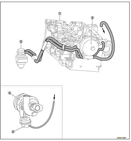
1. Cylinder head
2. Turbocharger boost control solenoid
valve
3. Vacuum pump
4. Turbocharger
5. Turbocharger boost control actuator
NOTE
: Do not use soapy water or any type of solvent while installing vacuum hose.
Turbocharger boost control : System Description
TURBOCHARGER BOOST CONTROL
The turbocharger system consists of a solenoid valve connected to the vacuum pump circuit; this enables the vanes to be controlled by a diaphragm so as to adjust the overpressure in the air inlet circuit.
EGR system : System Description
EGR SYSTEM
EGR Valve Control
The EGR (exhaust gas recirculation) system consists of a direct current EGR
volume control valve fitted with a
EGR volume control valve control position sensor. The EGR volume control valve
is controlled in a closed-loop
via the EGR volume control valve control position sensor. Up to a certain rate,
exhaust gas recirculation
enables nitrogen oxide (NOx) emissions to be reduced significantly.
EGR Cooler The EGR cooler reduces the volume of the EGR gas. As this volume is reduced, the quantity of EGR introduced in the cylinder increases and Nox emissions can be reduced more.
Measurement of the Fresh Air Flow The flow of fresh air entering the engine is calculated by a mass air flow sensor (ratiometric hot-wire sensor).
An intake air temperature sensor is integrated into the mass air flow sensor.
The mass air flow sensor facilitates control of the quantity of exhaust gas sent for recirculation, thus ensuring the best possible recirculation rates. Air flow measurement allows closed-loop control via the EGR valve.
Idle speed control : System Diagram
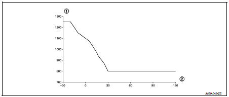
1. Engine speed in rpm 2. Engine coolant temperature ?°C
Idle speed control : System Description
The ECM is responsible for regulating the idle speed as a function of the idle speed set point which it calculates.
• The idle speed set point is dependent on:
- Engine coolant temperature
- Emission control program
- Air conditioning requirement
- Gear engaged
- Electrical load
- Battery voltage
Engine torque control : System Description
The torque structure is the system which translates the driver's request into a torque supplied by the engine. It is required for certain functions such as the electronic stability program (ESP), the automatic gearbox or the sequential gearbox if fitted).
Each inter-system (ESP, automatic gearbox, sequential gearbox) sends the ECM a torque request via the CAN communication. The computer arbitrates between the inter-system torque requests and the driver's request (comprised of the accelerator pedal or the cruise control/speed limiter function). The result of the arbitration gives the torque set point.
From this torque set point, the computer determines the quantity of fuel to be injected (injection duration and number of injections) and the amount of air required (turbocharging pressure and EGR rate) so that the engine is able to provide the torque required in the best possible conditions (in terms of smooth running performance, pollutantemissions, etc.).
Glow control : System Description
Glow control involves controlling the glow plugs and the glow plugs "on" indicator light on the instrument panel (via the can communication). The glow plugs are activated by a relay box and the power is provided by the battery.
After the ignition is switched on. Preheating is activated for a period of time. The indicator light comes on for the activation period which is dependent on the battery voltage, barometric pressure and engine coolant temperature.
When the engine coolant temperature is below a certain threshold, a postheating function enables combustion stability, and thereby engine operation, to be improved (reduction in unburnt fuel and pollutant emissions).
Cooling fan control : System Diagram
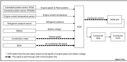
Cooling fan control : System Description
INPUT/OUTPUT SIGNAL CHART
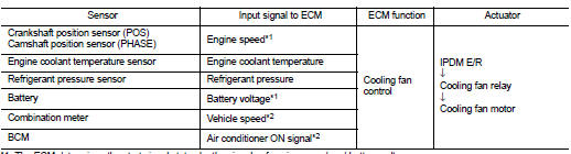
*1: The ECM determines the start signal status by the signals of engine speed and battery voltage.
*2: This signal is sent to ECM through CAN communication line.
SYSTEM DESCRIPTION
ECM controls cooling fan speed corresponding to vehicle speed, engine coolant temperature, refrigerant pressure, air conditioner ON signal. Then control system has 3-step control [HIGH/LOW/OFF].
Cooling Fan Operation With The Engine Running
Cooling fan operate is guaranteed by a 2-speed fan assembly (LOW speed and HIGH
speed).The ECM
requests the IPDM E/R to actuate them via the can communication. To provide
cooling:
• Engine running
- LOW speed is actuated when the engine coolant temperature exceeds 99?°C (210?°F)
and is deactivated
when it drops below 96 ?°C (205?°F).
- HIGH speed is actuated when the engine coolant temperature exceeds 102?°C (216?°F) and is deactivated when it drops below 99?°C (210?°F).
• If the engine coolant temperature exceeds the threshold of 115?°C (239?°F), the ECM requests the IPDM E/R, via the CAN communication, to switch off the air conditioning compressor so as to reduce the load on the engine and attempt to limit the rise in temperature. The cut-off request is cancelled if the engine coolant temperature drops below 110?°C (230?°F).
• If a malfunction in the engine coolant temperature sensor circuit is detected, the ECM requests that HIGH speed operation.
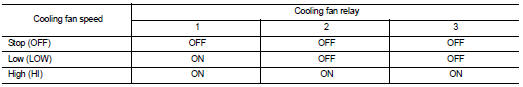
Cooling Fan Relay Operation The ECM controls cooling fan relays through CAN communication line.
DPF (Diesel particulate filter) : System Description
SYSTEM DESCRIPTION
ECM estimates the amount of particulate matter in diesel particulate filter based on the mileage and the exhaust back pressure before it. ECM automatically performs regeneration when the amount of particulate matter in diesel particulate filter reaches the specified level. When performing regeneration, ECM raise the exhaust gas temperature to activate Oxidation Catalyst. ECM performs the followings to raise exhaust gas temperature.
• Closing throttle valve to reduce intake air volume
• Retarding fuel injection timing
• Injecting additional fuel into combustion chamber during exhaust stroke (post
injection)
• Performing EGR control
• Performing exhaust fuel injector control
• Performing thermoplunger control unit
When exhaust gas temperature reaches the specified value, oxidation catalyst is activated. The trapped particulate matter is burned through a catalytic reaction using exhaust gas heat at 650 ?°C.
Automatic speed control devicE (ASCD) : System Diagram
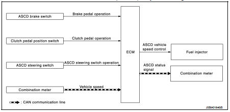
Automatic speed control devic (ASCD) : System Description
INPUT/OUTPUT SIGNAL CHART
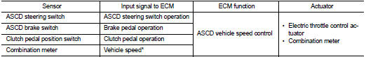
*: This signal is sent to the ECM via the CAN communication line BASIC ASCD SYSTEM
• Automatic Speed Control Device (ASCD) allows a driver to keep vehicle at predetermined constant speed without depressing accelerator pedal. Driver can be set the vehicle speed in the set speed range.
• ECM controls throttle angle of electric throttle control actuator to regulate engine speed.
• Operation status of ASCD is indicated in combination meter.
• If any malfunction occurs in the ASCD system, it automatically deactivates the ASCD control.
Refer to EC-832, "AUTMATIC SPEED CONTROL DEVICE (ASCD) : Switch Name and Function" for ASCD operating instructions.
CAUTION:
Always drive vehicle in a safe manner according to traffic conditions and obey
all traffic laws.
Speed limiter : System Diagram
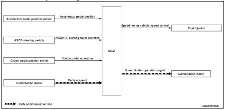
Speed limiter : System Description
INPUT/OUTPUT SIGNAL CHART
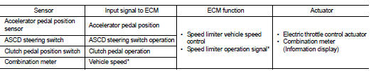
*: This signal is sent to the ECM through CAN communication line
BASIC SPEED LIMITER SYSTEM
• Speed limiter is a system that enables to restrict the vehicle speed within the set speed that is selected by the driver. Driver can be set the vehicle speed in the set speed range.
• ECM controls throttle angle of electric throttle control actuator to regulate vehicle speed.
• Operation status of speed limiter is indicated on the information display in the combination meter.
• Unlike cancel conditions for ASCD, the speed limiter is not cancelled even when the clutch pedal is depressed. ECM detects a clutch pedal position switch signal and controls engine revolutions to maintain a set speed when shifting gears.
• If any malfunction occurs in speed limiter system, it automatically deactivates the speed limiter control.
Refer to EC-833, "SPEED LIMITER : Switch Name and Function" for speed limiter operating instructions.
CAUTION:
Always drive vehicle in safe manner according to traffic conditions and obey all
traffic laws.
NOTE:
Since the speed limiter is controlled by the electric throttle control actuator, vehicle speed may exceed a set speed during downhill driving.
Can communication : System Description
CAN (Controller Area Network) is a serial communication line for real time application. It is an on-vehicle multiplex communication line with high data communication speed and excellent error detection ability. Many electronic control units are equipped onto a vehicle, and each control unit shares information and links with other control units during operation (not independent). In CAN communication, control units are connected with 2 communication lines (CAN H line, CAN L line) allowing a high rate of information transmission with less wiring.
Each control unit transmits/receives data but selectively reads required data only.
Refer to LAN-31, "CAN COMMUNICATION SYSTEM : CAN Communication Signal Chart", about CAN communication for detail.
 Component parts
Component Parts Location
ENGINE ROOM COMPARTMENT
Top View
1. Priming pump
2. Turbocharger boost control solenoid
valve
3. Cooling fan motor
4. Refrigerant pressure sensor
5. IPDM E/R
6. ...
 Operation
Autmatic speed control device (ASCD) : Switch Name and Function
SWITCHES AND INDICATORS
NOTE:
Shared with speed limiter switch.
1. CRUISE indicator lamp
2. SET indicator lamp
3. CANCEL switc ...
Other materials:
Wiring diagram
POWER SOCKET
Wiring Diagram
For connector terminal arrangements, harness layouts, and alphabets in a
(option abbreviation; if not
described in wiring diagram), refer to GI-12, "Connector Information/Explanation
of Option Abbreviation".
...
Precaution Necessary for Steering Wheel Rotation after Battery Disconnect
NOTE:
• Before removing and installing any control units, first turn the ignition
switch to the LOCK position, then disconnect
both battery cables.
• After finishing work, confirm that all control unit connectors are connected
properly, then re-connect both
battery cables.
• Always us ...
CD/USB memory care and cleaning
CD
• Handle a CD by its edges. Never touch the surface of the disc. Do not bend
the disc.
• Always place the discs in the storage case when they are not being used.
• To clean a disc, wipe the surface from the center to the outer edge using a clean,
soft cloth. Do not wipe the d ...
