Nissan Juke Service and Repair Manual : On board diagnostic (OBD) system
Diagnosis Description
The ECM controls the display on the instrument panel of certain information relating to the operation of the engine.
Four functions are involved here: The OBD malfunction indicator [MI (Yellow)] for the EOBD (European On Board Diagnostics), the pre/post heating, the engine coolant temperature and engine malfunction [MI (Red)].
These four functions are represented by four lights given out by the ECM GLOW LAMP
This lamp indicates that the glow control system has been activated.
ENGINE COOLANT TEMPERATURE LIGHT
This light is used as an indicator of engine overheating.
• In the event of overheating, it is up to the driver whether to stop the vehicle or not.
MALFUNCTION INDICATOR
The OBD malfunction indicator [MI (Yellow)] is used to alert the driver to the existence of engine control system malfunctions involving excessive pollution or if the EOBD system is deactivated.
The ECM makes a request for lighting of the MI (Yellow) only where there is a malfunction present at the end of three consecutive cycles.
The 3-second visual check upon powering up (automatic test procedure controlled by the IPDM E/R) is performed by the ECM.
In the event of a confirmed OBD malfunction by lighting of the MI, no flashing of the light must be observed following the lighting test.
DTCs Causing MI to Light
ENGINE WARNING LIGHT
In the event of an engine malfunction, the ECM may request the display of an engine warning light [MI (Red)].
HOW TO ERASE DTC, 1ST TRIP DTC AND 2ND TRIP DTC
 With CONSULT-III
NOTE
:
If the ignition switch stays ON after repair work, be sure to turn ignition
switch OFF once. Wait at least 10 seconds
and then turn it ON (engine stopped) again.
1. Select ???ENGINE??? with CONSULT-III.
2. Select ???SELF-DIAG RESULTS???.
3. Touch ???ERASE???. (DTC in ECM will be erased)
MI OPERATION CHART
Some malfunction must switch on MI to warn driver, that his engine emissions exceed OBD thresholds (Euro 3 x 2.5).
The rule is to switch on MI after 3 consecutive driving cycles (engine start + engine stop + power latch) with a present OBD malfunction.
To switch off the MI (without CONSULT-III), vehicle has to drive 3 consecutive cycles without present OBD malfunction.
Ignition switch OFF → ON transition, MI remains switched on in pre-drive check mode until engine start. If MI does not switch off whereas engine is running, there is at least one present OBD malfunction.
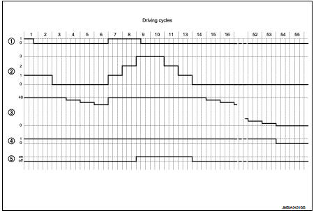
1. Present malfunction 2. Driving cycle counter 3. Warm up cycle counter 4. Memorised malfunction 5. MI state
NOTE
: Driving cycle and warm up cycle are both detected in the same cycle.
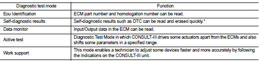
Consult-III Function
FUNCTION
*: The following emission-related diagnostic information is cleared when the ECM memory is erased.
• Diagnostic trouble codes
SELF-DIAGNOSTIC MODE
Self Diagnostic Item
Regarding items detected in ???SELF-DIAG RESULTS??? mode, refer to EC-855, "DTC
Index".
DATA MONITOR MODE
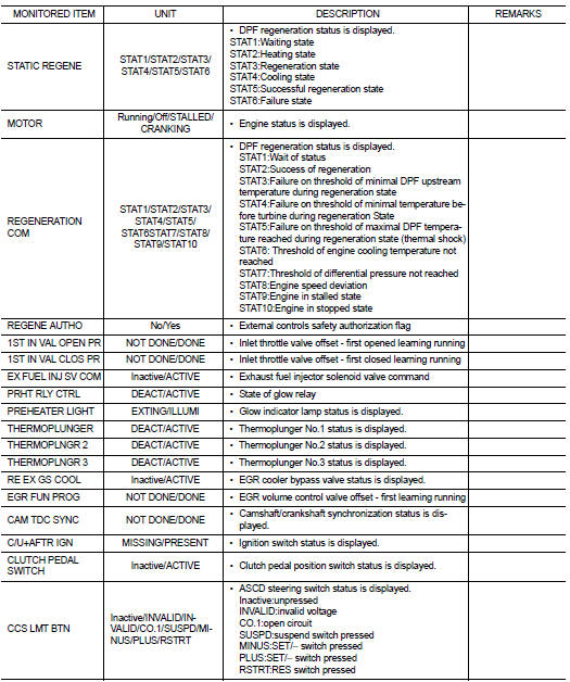
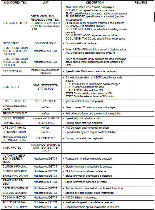
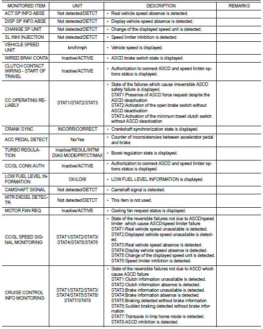
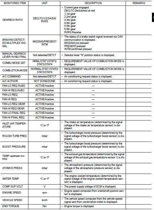
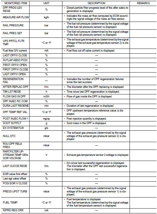
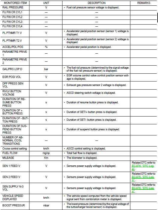
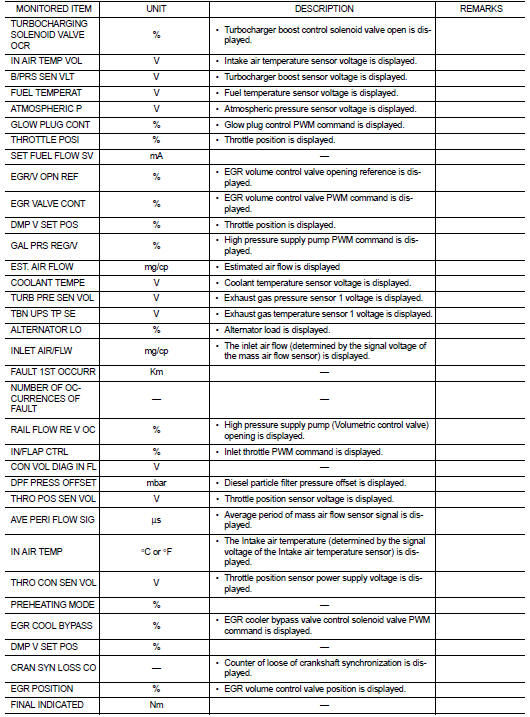
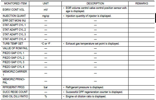
NOTE
:
Any monitored item that does not match the vehicle being diagnosed is deleted
from the display automatically.
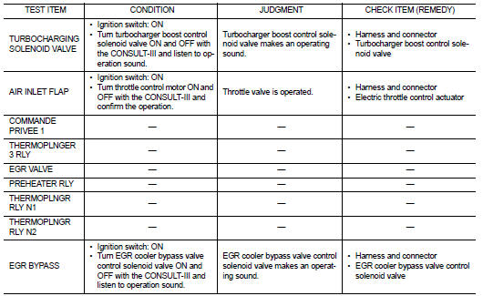
ACTIVE TEST MODE
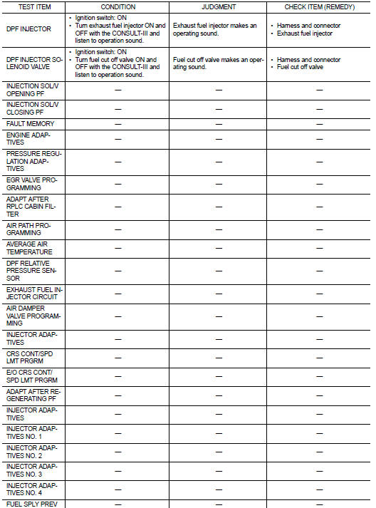
WORK SUPPORT MODE
Work Item
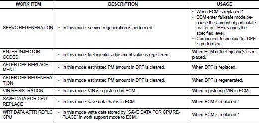
*: The necessary operation is different depending on the operation result of ECM data save or write. Always perform the operation according to procedures. Refer to EC-879, "Work Procedure".
 Operation
Autmatic speed control device (ASCD) : Switch Name and Function
SWITCHES AND INDICATORS
NOTE:
Shared with speed limiter switch.
1. CRUISE indicator lamp
2. SET indicator lamp
3. CANCEL switc ...
 ECU diagnosis information
ECM
Reference Value
TERMINAL LAYOUT
PHYSICAL VALUES
NOTE:
• ECM is located in the engine room left side near battery.
• When disconnecting ECM harness connector (1), loosen (B) it with
le ...
Other materials:
ANTI-HIJACK function does not operate
Diagnosis Procedure
1.CHECK “DOOR LOCK–UNLOCK SET” SETTING IN “WORK SUPPORT”
1. Select “DOOR LOCK” of “BCM” using CONSULT-III.
2. Select “DOOR LOCK-UNLOCK SET” in “WORK SUPPORT” mode.
3. Check “DOOR LOCK-UNLOCK SET” in “WORK SUPPORT”
Refer to DLK-501, "DOO ...
Precaution for Supplemental Restraint System (SRS) "AIR BAG" and "SEAT BELT
PRE-TENSIONER"
The Supplemental Restraint System such as “AIR BAG” and “SEAT BELT PRE-TENSIONER”,
used along
with a front seat belt, helps to reduce the risk or severity of injury to the
driver and front passenger for certain
types of collision. Information necessary to service the system safely is
...
U1000 can comm circuit
Description
CAN (Controller Area Network) is a serial communication line for real time
applications. It is an on-vehicle multiplex
communication line with high data communication speed and excellent error
detection ability. Modern
vehicle is equipped with many electronic control unit, and eac ...
