Nissan Juke Service and Repair Manual : ECU diagnosis information
ECM
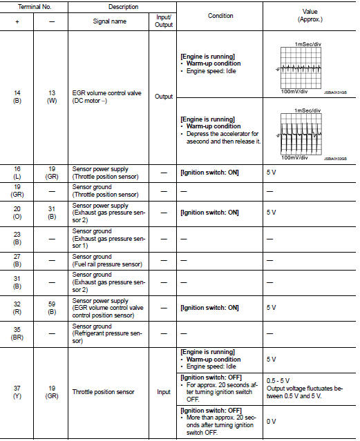
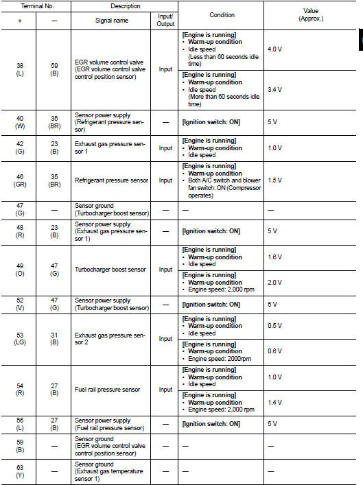
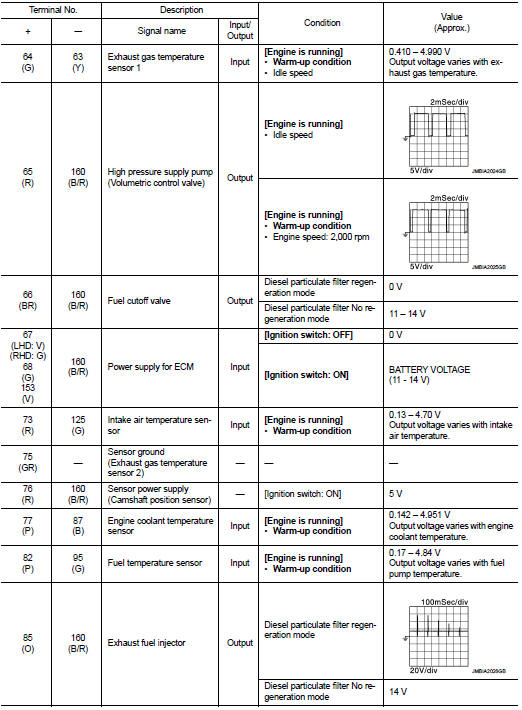
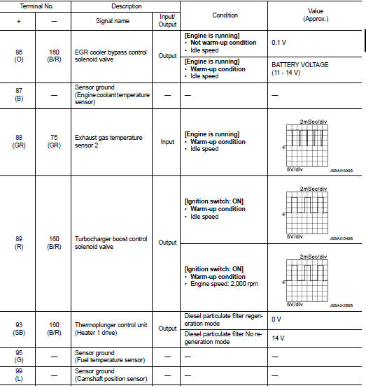
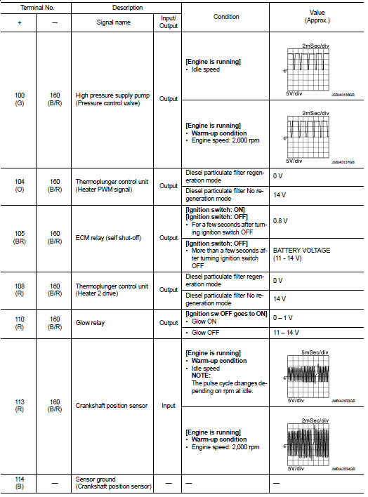
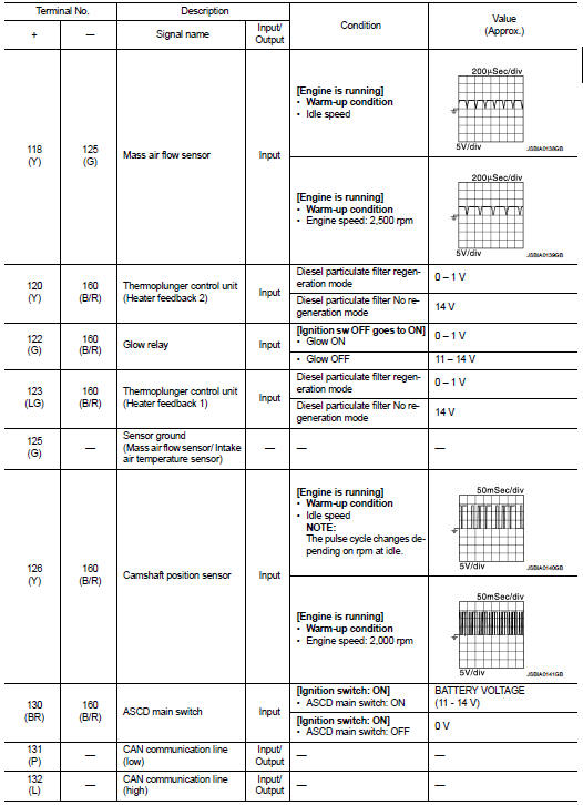
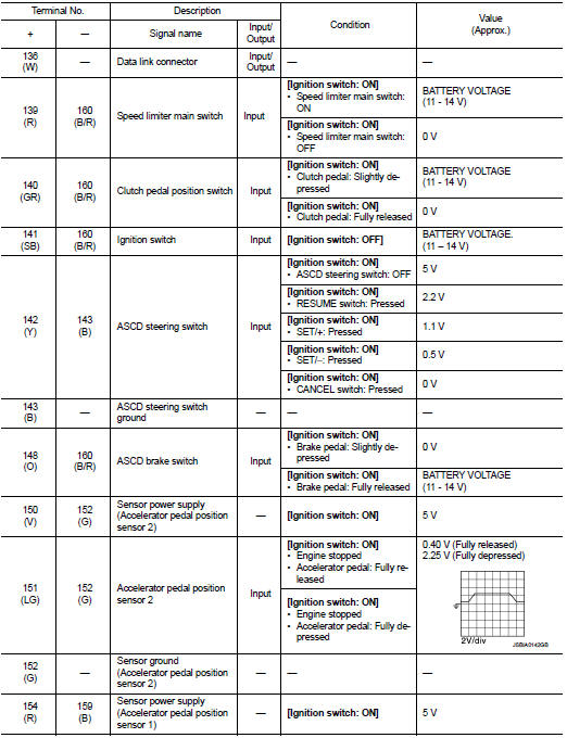
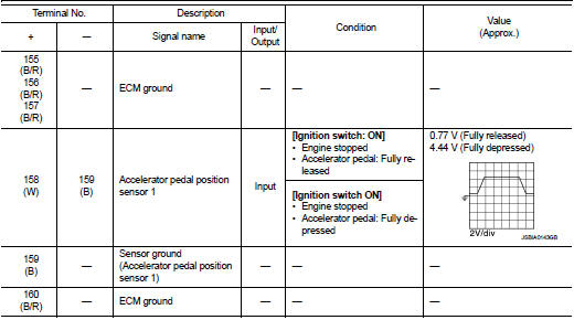
Reference Value
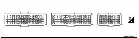
TERMINAL LAYOUT
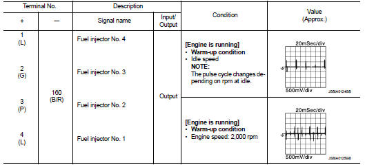
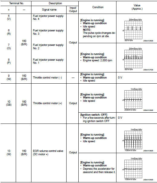
PHYSICAL VALUES
NOTE
:
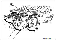
• ECM is located in the engine room left side near battery.
• When disconnecting ECM harness connector (1), loosen (B) it with levers as far as they will go as shown in the figure.
2 : ECM
A : Fasten
• Pulse signal is measured by CONSULT-III.
DTC Index
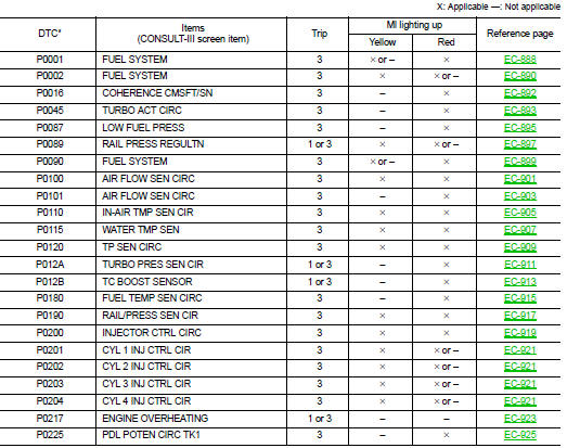
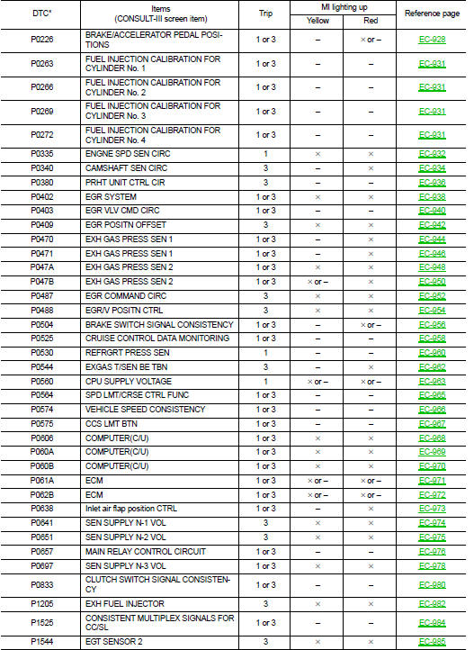
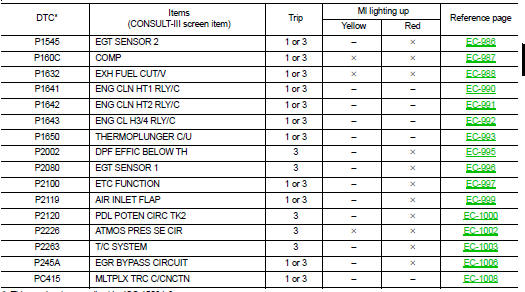
*: This number is prescribed by ISO 15031-6.
 On board diagnostic (OBD) system
Diagnosis Description
The ECM controls the display on the instrument panel of certain information
relating to the operation of the
engine.
Four functions are involved here: The OBD malfunction ...
 Wiring diagram
Engine control system
Wiring Diagram
For connector terminal arrangements, harness layouts, and alphabets in a
(option abbreviation; if not
described in wiring diagram), refer to GI-12, "Conne ...
Other materials:
P0544 EGT sensor 1
DTC Logic
DTC DETECTION LOGIC
Diagnosis Procedure
1.CHECK GROUND CONNECTIONS
1. Turn ignition switch OFF.
2. Check ground connection E38. Refer to Ground inspection in GI-44, "Circuit
Inspection".
Is the inspection result normal?
YES >> GO TO 2.
NO >> Repair or ...
Diagnosis system (ECM)
Diagnosis description
Diagnosis description : 1st Trip Detection
Logic and Two Trip Detection Logic
When a malfunction is detected for the first time, 1st trip DTC and 1st trip
Freeze Frame data are stored in the
ECM memory. The MIL will not illuminate at this stage. <1st trip>
If the s ...
Front door
Exploded View
1. Front door panel
2. Grommet
3. Door hinge (upper)
4. Door hinge (lower)
5. Door check link
6. Bumper rubber
7. Door pad
8. Door striker
9. TORX bolt
10. Grommet
: Do not reuse
: N·m (kg-m, in-lb)
: N·m (kg-m, ft-lb)
: Body grease
Door assembly
DOOR ASSEMBLY ...
