Nissan Juke Service and Repair Manual : Wiring diagram
Engine control system
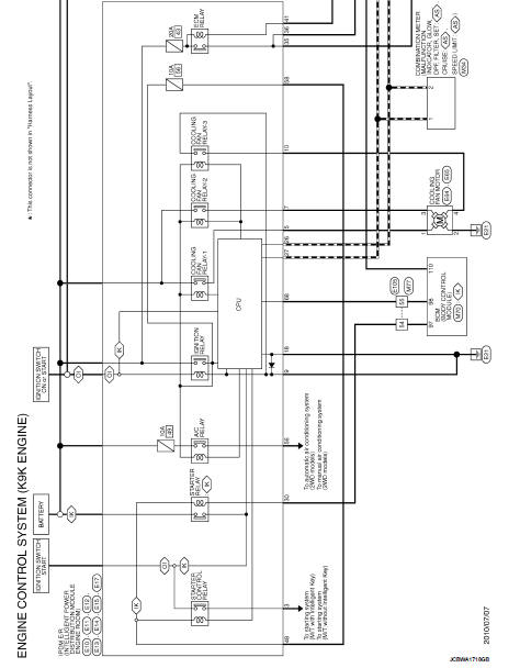
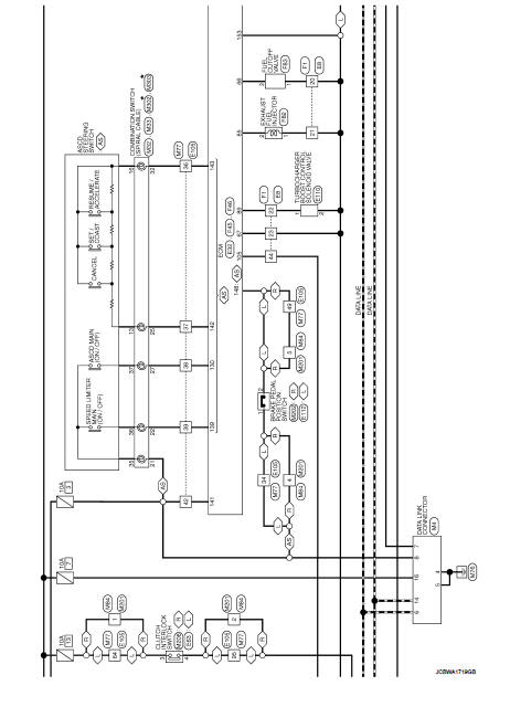
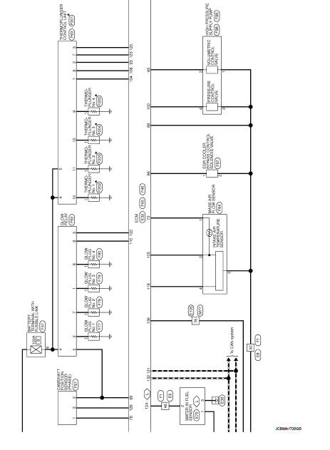
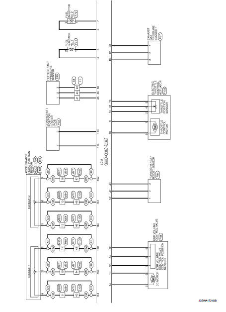
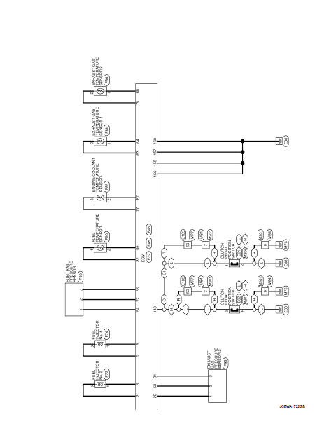
Wiring Diagram
For connector terminal arrangements, harness layouts, and alphabets in a
 (option abbreviation; if not
described in wiring diagram), refer to GI-12, "Connector Information/Explanation
of Option Abbreviation".
 ECU diagnosis information
ECM
Reference Value
TERMINAL LAYOUT
PHYSICAL VALUES
NOTE:
• ECM is located in the engine room left side near battery.
• When disconnecting ECM harness connector (1), loosen (B) it with
le ...
 Basic inspection
...
Other materials:
Luggage floor trim
Exploded View
2WD models
1. Rear pillar cap RH
2. Luggage side upper finisher RH
3. Luggage side lower finisher RH
4. Luggage floor board
5. Luggage side upper finisher LH
6. Rear pillar cap LH
7. Luggage side lower finisher LH
8. Seat belt hook LH
9. Shock absorber mask LH
10. Lug ...
U0073 communication bus A off
Description
CAN (Controller Area Network) is a serial communication line for real-time
application. It is an on-vehicle multiplex
communication line with high data communication speed and excellent malfunction
detection ability.
Many electronic control units are equipped onto a vehicle, and ...
Power transistor
Exploded View
1. A/C unit assembly
2. Blower fan resistor*1
3. Sub harness*1
4. Power transistor*2
5. Sub harness*2
6. Blower motor
• *1: Manual air conditioner
• *2: Automatic air conditioner
Removal and Installation
REMOVAL
1. Remove instrument panel assembly. Refer to IP-13, ...
