Nissan Juke Service and Repair Manual : U1000 can comm circuit
Description
CAN (Controller Area Network) is a serial communication line for real time applications. It is an on-vehicle multiplex communication line with high data communication speed and excellent error detection ability. Modern vehicle is equipped with many electronic control unit, and each control unit shares information and links with other control units during operation (not independent). In CAN communication, control units are connected with 2 communication lines (CAN-H line, CAN-L line) allowing a high rate of information transmission with less wiring. Each control unit transmits/receives data but selectively reads required data only.
CAN Communication Signal Chart. Refer to LAN-31, "CAN COMMUNICATION SYSTEM : CAN Communication Signal Chart".
DTC Logic
DTC DETECTION LOGIC
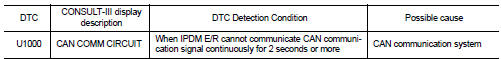
Diagnosis Procedure
1.PERFORM SELF DIAGNOSTIC
1. Turn the ignition switch ON and wait for 2 seconds or more.
2. Check ŌĆ£Self Diagnostic ResultŌĆØ of IPDM E/R.
Is DTC ŌĆ£U1000ŌĆØ displayed? YES >> Refer to LAN-17, "Trouble Diagnosis Flow Chart".
NO >> Refer to GI-42, "Intermittent Incident".

 B2098 ignition relay on stuck
Description
The ignition relay integrated in IPDM E/R is operated with ignition switch ON
signal from the ignition switch.
DTC Logic
DTC DETECTION LOGIC
1.PERFORM DTC CONFIRMATION PROCEDURE
1 ...
Other materials:
Component parts
Component Parts Location
ENGINE ROOM COMPARTMENT
Top View
1. Priming pump
2. Turbocharger boost control solenoid
valve
3. Cooling fan motor
4. Refrigerant pressure sensor
5. IPDM E/R
6. ECM
7. Mass air flow sensor (with intake air
temperature sensor)
8. Electric throttle control act ...
RAB system operation
RAB warning light and dedicated system warning indicator
Steering-wheel-mounted control switches (located on the left side)
Center infotainment and information display
The RAB system is active whenever the shift lever is placed in the R (R ...
Avoiding collision and rollover
WARNING
Failure to operate this vehicle in a safe, alert, and prudent manner significantly increases the risk of a dangerous situation and may result in an immediate loss of control or a severe accident.
Be alert, anticipate potential hazards, and drive defensively at all times behind the ...
