Nissan Juke Service and Repair Manual : B2098 ignition relay on stuck
Description
The ignition relay integrated in IPDM E/R is operated with ignition switch ON signal from the ignition switch.
DTC Logic
DTC DETECTION LOGIC
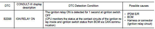
1.PERFORM DTC CONFIRMATION PROCEDURE
1. Turn ignition switch ON.
2. Check DTC in “Self Diagnostic Result” mode of “IPDM E/R” using CONSULT-III.
Is DTC detected? YES >> Refer to PCS-60, "Diagnosis Procedure".
NO >> INSPECTION END.
Diagnosis Procedure
1.CHECK IGNITION SWITCH ON SIGNAL
Check voltage between BCM harness connectors and the ground.
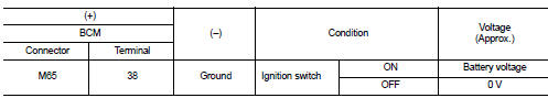
Is the measurement value normal? YES >> Replace BCM. Refer to BCS-161, "Removal and Installation".
NO >> GO TO 2.
2.CHECK IGNITION SWITCH ON SIGNAL CIRCUIT
1. Turn the ignition switch OFF.
2. Disconnect IPDM E/R harness connectors.
3. Check continuity between IPDM E/R harness connectors and BCM harness connectors.
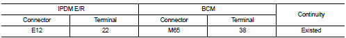
Does continuity exist? YES >> Replace IPDM E/R. Refer to PCS-63, "Removal and Installation".
NO >> Repair the harness or connector.
 U1000 can comm circuit
Description
CAN (Controller Area Network) is a serial communication line for real time
applications. It is an on-vehicle multiplex
communication line with high data communication speed and excelle ...
 B2099 ignition relay off stuck
Description
The ignition relay integrated in IPDM E/R is operated with ignition switch ON
signal from the ignition switch.
DTC Logic
DTC DETECTION LOGIC
NOTE:
When IPDM E/R power supply volta ...
Other materials:
Service
• Never use electrical test equipment to check SRS circuits unless instructed
to in this Service Manual.
• Before servicing the SRS, turn ignition switch OFF, disconnect battery
negative terminal and wait at least 3
minutes.
For approximately 3 minutes after the battery negative termina ...
Control cable
Exploded View
1. Control cable
2. Lock plate
3. Transaxle assembly
4. Bracket A
5. Bracket B
6. CVT shift selector assembly
A: Manual lever B: Grommet
: N·m (kg-m, ft-lb)
: N·m (kg-m, in-lb)
Removal and Installation
INSTALLATION
CAUTION:
Always apply the parking brake before per ...
EGR valve
Exploded View
1. EGR valve assembly
2. Clamp
3. EGR tube
4. Air inlet tube
5. O-ring
6. Gasket
7. EGR cooler
8. Gasket
9. EGR volume control valve housing
10. Gasket
11. Electric throttle control actuator
12. Gasket
13. EGR volume control valve
14. Clamp
15. Cooling hose
...
