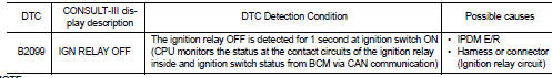
Nissan Juke Service and Repair Manual : B2099 ignition relay off stuck
Description
The ignition relay integrated in IPDM E/R is operated with ignition switch ON signal from the ignition switch.
DTC Logic
DTC DETECTION LOGIC
NOTE
:
When IPDM E/R power supply voltage is low (Approx. 7 - 8 V for about 1 second),
the “DTC: B2099” may be detected.
1.PERFORM DTC CONFIRMATION PROCEDURE
1. Turn ignition switch ON.
2. Check DTC in “Self Diagnostic Result” mode of “IPDM E/R” using CONSULT-III.
Is DTC detected? YES >> Refer to PCS-61, "Diagnosis Procedure".
NO >> INSPECTION END.
Diagnosis Procedure
1.CHECK IGNITION SWITCH ON SIGNAL CIRCUIT
1. Turn the ignition switch OFF.
2. Disconnect IPDM E/R harness connector and BCM harness connector.
3. Check continuity between IPDM E/R harness connectors and BCM harness connectors.
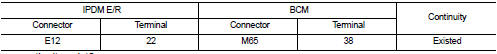
Does continuity exist? YES >> Replace IPDM E/R. Refer to PCS-63, "Removal and Installation".
NO >> Repair the harness or connector.
 B2098 ignition relay on stuck
Description
The ignition relay integrated in IPDM E/R is operated with ignition switch ON
signal from the ignition switch.
DTC Logic
DTC DETECTION LOGIC
1.PERFORM DTC CONFIRMATION PROCEDURE
1 ...
 Power supply and ground circuit
Diagnosis Procedure
1.CHECK FUSES AND FUSIBLE LINK
Check that the following IPDM E/R fuses or fusible links are not blown.
Is the fuse fusing?
YES >> Replace the blown fuse or fusible link ...
Other materials:
C1130 engine signal
DTC Logic
DTC DETECTION LOGIC
DTC CONFIRMATION PROCEDURE
1.PRECONDITIONING
If “DTC CONFIRMATION PROCEDURE” has been previously conducted, always turn
ignition switch OFF and
wait at least 10 seconds before conducting the next test.
>> GO TO 2.
2.CHECK DTC DETECTION
With CON ...
Engine oil and oil filter recommendation
1. API certification mark
2. API service symbol
Selecting the correct oil
It is essential to choose the correct grade, quality, and viscosity engine oil
to ensure satisfactory engine life and performance, see “Capacities and recommended
fuel/lubricants” . NISSAN recommends the use of an ...
Door motor
Diagnosis Procedure
NOTE:
If all of door motor DTCs are detected, check this circuit.
1.CHECK DOOR MOTOR POWER SUPPLY
1. Turn ignition switch ON.
2. Check voltage between intake door motor harness connector and ground.
Is the inspection result normal?
YES >> GO TO 2.
NO >> ...
