Nissan Juke Service and Repair Manual : Oil pan (upper)
Exploded View
With Oil Cooler
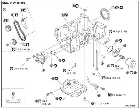
1. Rear oil seal
2. O-ring
3. Oil pan (upper)
4. Oil pump chain tensioner (for oil
pump drive chain)
5. Oil pump drive chain
6. Crankshaft sprocket
7. Oil pump sprocket
8. Oil pump
9. O-ring
10. O-ring
11. Oil pan (lower)
12. Oil pan drain plug
13. Drain plug washer
14. Oil level sensor
15. Relief valve
16. Connector bolt
17. Oil filter
18. Oil cooler
19. O-ring
A. Refer to EM-182
B. Refer to LU-28
C. Oil pan (lower) side
 : Always replace after every
disassembly.
 : N·m (kg-m, in-lb)
 : N·m (kg-m, ft-lb)
 : Sealing point
 : Should be lubricated with oil.
With Out Oil Cooler
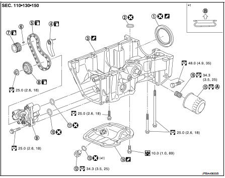
1. Rear oil seal
2. O-ring
3. Oil pan (upper)
4. Oil pump chain tensioner (for oil
pump drive chain)
5. Oil pump drive chain
6. Crankshaft key
7. Crankshaft sprocket
8. Oil pump sprocket
9. Oil pump
10. O-ring
11. O-ring
12. Oil pan drain plug
13. Drain plug washer
14. Oil pan (lower)
15. Oil filter
16. Oil filter stud bolt
A. Refer to EM-182
B. Refer to LU-28
C. Oil pan (lower) side
: Always replace after every
disassembly.
: N·m (kg-m, in-lb)
: N·m (kg-m, ft-lb)
: Sealing point
: Should be lubricated with oil..
Removal and Installation
NOTE
:
The oil strainer and oil pump are included in the oil pan (upper). Individual
disassembly is prohibited.
REMOVAL
1. Remove the oil pan (lower). Refer to EM-169, "Exploded View".
2. Remove oil pump sprocket and crankshaft sprocket together with oil pump drive chain. Refer to EM-181, "Exploded View".
3. Remove oil pan (upper) with the following procedure.
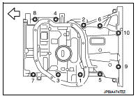
a. Loosen oil pan (upper) mounting bolts in the reverse of the order as shown in the figure.
 : Engine front
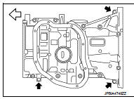
b. Insert a flat-bladed offset screwdriver into the arrow (
) in the
figure and open up a crack between the oil pan (upper) cylinder
block.
![c. Insert the seal cutter [SST: KV10111100] between the oil pan](images/books/335/5/index.101.gif) : Engine front
: Engine front
c. Insert the seal cutter [SST: KV10111100] between the oil pan (upper) and cylinder block. Slide seal cutter by tapping on the side of tool with a hammer.
CAUTION:
• Be careful not to damage the mating surface.
• A more adhesive liquid gasket is applied compared to previous types when shipped, so it should not be forced off using a screwdriver, etc. outside the indicated location.
• Never remove oil pump and oil strainer from oil pan (upper).
4. Remove rear oil seal from crankshaft.
INSTALLATION
1. Install the oil pan (upper) in the following procedure: a. Use scraper to remove old liquid gasket from mating surfaces.
• Also remove the old liquid gasket from mating surface of cylinder block.
• Remove old liquid gasket from the bolt holes and threads.
CAUTION:
Never scratch or damage the mating surfaces when cleaning off old liquid gasket.
b. Install O-ring to the cylinder block.
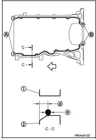
c. Apply a continuous bead of liquid gasket (C) with the tube presser (commercial service tool) to areas as shown in the figure.
Use Genuine Liquid Gasket or equivalent.
A : 2 mm (0.07 in) protruded to outside
B : 2 mm (0.07 in) protruded to rear oil seal mounting side
d : 5.5 - 7.5 mm (0.217 - 0.295 in)
e : φ4.0 - 5.0 mm (0.157 - 0.197 in)
 : Engine front side
 : Engine out side
A : Excess of 2 mm or more outward
B : Excess of 2 mm or more in the rear oil seal mounting direction
CAUTION:
Attaching should be done within 5 minutes after coating.
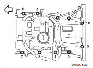
d. Tighten bolts in the numerical order as shown in the figure.
: Engine front
CAUTION:
Install avoiding misalignment of both oil pan gasket and Oring.
• The bolts are different according to the installation position.
Refer to the numbers as shown in the figure.
M8×180 mm (7.09 in) : No. 9, 10 M8×25 mm (0.98 in) : No. 3, 4, 7, 8 M8×90 mm (3.54 in) : No. 1, 2, 5, 6
2. Install rear oil seal with the following procedure:
CAUTION:
• The installation of rear oil seal should be completed within 5 minutes after
installing oil pan
(upper).
• Never touch oil seal lip.
a. Wipe off any liquid gasket protruding to the rear oil seal mounting part of oil pan (upper) and cylinder block using a spatula.
b. Apply the liquid gasket lightly to entire outside area of new rear oil seal.
Use Genuine Liquid Gasket or equivalent.
c. Press-fit the rear oil seal using a drift with outer diameter 113 mm (4.45 in) and inner diameter 90 mm (3.54 in) (commercial service tool) (A).
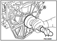
• Press-fit to the dimensions specified as shown in the figure.
1 : Rear oil seal
A : Rear end surface of cylinder block
b : 0 - 0.5 mm (0 - 0.020 in)
CAUTION:
• Never touch the grease applied to the oil seal lip.
• Be careful not to damage the rear oil seal mounting part of oil pan (upper) and cylinder block or the crankshaft.
• Press-fit straight check that oil seal does not curl or tilt.
d. After press-fitting the rear oil seal, completely wipe off any liquid gasket protruding to rear end surface side.
3. Install in the reverse order of removal, for the rest of parts.
Inspection
INSPECTION AFTER INSTALLATION
1. Check engine oil level and adjust engine oil. Refer to LU-25, "Inspection".
2. Check for leakage of engine oil when engine is warmed.
3. Stop engine and wait for 10 minutes.
4. Check engine oil level again. Refer to LU-25, "Inspection".
 Engine unit
Disassembly
1. Remove intake manifold. Refer to EM-163, "Exploded View".
2. Remove exhaust manifold. Refer to EM-166, "Exploded View".
3. Remove oil pan (lower). Refer to EM-16 ...
 Cylinder block
Exploded View
1. Crankshaft position sensor (POS) cover
2. Crankshaft position sensor (POS)
3. O-ring
4. Drain plug
5. Cylinder block
6. Oil level gauge
7. Oil level gauge guide
8. O-ri ...
Other materials:
Front oil seal
Exploded View
1. Rear final drive assembly
2. Front oil seal
3. Companion flange
4. Companion flange lock nut
A. Oil seal lip
: Vehicle front
: N·m (kg-m, ft-lb)
: Never reuse parts
: Apply multi purpose grease
: Apply gear oil.
Removal and Installation
REMOVAL
CAUTION:
Verify ide ...
4WD warning lamp
Component Function Check
1.CHECK 4WD WARNING LAMP FUNCTION
1. Turn the ignition switch ON.
2. Check that 4WD warning lamp turns on.
Is the inspection result normal?
YES >> INSPECTION END
NO >> Proceed to diagnosis procedure. Refer to DLN-80, "Diagnosis Procedure".
Diag ...
Cooling fan
Exploded View
1. Fan motor
2. Fan shroud
3. Cooling fan
A. Apply on fan motor shaft
: Apply genuine high strength
thread locking sealant or equivalent.
: N·m (kg-m, in-lb)
Removal and Installation
REMOVAL
1. Drain engine coolant from radiator. Refer to CO-37, "Draining".
...
