Nissan Juke Service and Repair Manual : B26F9 cranking request circuit
DTC Logic
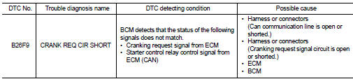
DTC DETECTION LOGIC
NOTE
:
• If DTC B26F9 is displayed with DTC U1000, first perform the trouble diagnosis
for DTC U1000. Refer to
BCS-83, "DTC Logic".
• If DTC B26F9 is displayed with DTC U1010, first perform the trouble diagnosis for DTC U1010. Refer to BCS-84, "DTC Logic".
DTC CONFIRMATION PROCEDURE
1.PERFORM DTC CONFIRMATION
1. Perform DTC CONFIRMATION PROCEDURE for DTC P1650. Refer to EC-366, "DTC Logic" (MR16DDT) or EC-725, "DTC Logic" (HR16DE).
2. Turn ignition switch ON.
3. Check DTC in “Self Diagnostic Result” mode of “BCM” using CONSULT-III.
Is DTC detected? YES >> Go to SEC-128, "Diagnosis Procedure".
NO >> INSPECTION END
Diagnosis Procedure
1.CHECK CRANKING REQUEST SIGNAL
1. Turn ignition switch ON.
2. Check voltage between BCM harness connector and ground under the following conditions.
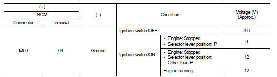
Is the inspection result normal? YES >> GO TO 3.
NO >> GO TO 2.
2.CHECK CRANKING REQUEST SIGNAL CIRCUIT
1. Turn ignition switch OFF.
2. Disconnect BCM connector.
3. Disconnect ECM connector.
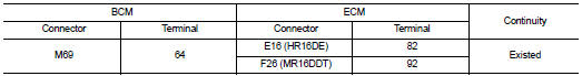
4. Check continuity between BCM harness connector and ECM harness connector.
5. Check continuity between BCM harness connector and ground.
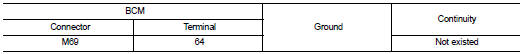
Is the inspection result normal? YES >> GO TO 3.
NO >> Repair or replace harness.
3.REPLACE BCM
1. Replace BCM. Refer to BCS-93, "Removal and Installation".
2. Perform initialization of BCM and registration of all Intelligent Keys using CONSULT-III.
For initialization and registration procedures, refer to CONSULT-III Operation Manual NATS-IVIS/NVIS.
3. Perform DTC CONFIRMATION PROCEDURE for DTC B26F9. Refer to SEC-128, "DTC Logic".
Is DTC detected? YES >> GO TO 4.
NO >> INSPECTION END
4.REPLACE ECM
Replace ECM.
Refer to EC-447, "Removal and Installation" (MR16DDT) or EC-805, "Removal and Installation" (HR16DE).
>> INSPECTION END
 B26F8 BCM
DTC Logic
DTC DETECTION LOGIC
NOTE:
DTC B26F8 can be detected even though the related circuit is not used in this
vehicle.
DTC CONFIRMATION PROCEDURE
1.PERFORM DTC CONFIRMATION PROCEDURE
1. ...
 B26FA cranking request circuit
DTC Logic
DTC DETECTION LOGIC
NOTE:
• If DTC B26FA is displayed with DTC U1000, first perform the trouble diagnosis
for DTC U1000. Refer to
BCS-83, "DTC Logic".
• If DTC B26FA is ...
Other materials:
C1115 wheel sensor
DTC Logic
DTC CONFIRMATION PROCEDURE
1.PRECONDITIONING
If “DTC CONFIRMATION PROCEDURE” has been previously conducted, always turn
ignition switch OFF and
wait at least 10 seconds before conducting the next test.
>> GO TO 2.
2.CHECK DTC DETECTION
With CONSULT-III.
1. Stat th ...
Transaxle assembly
Exploded View
CASE AND HOUSING
1. Differential side oil seal
2. Clutch housing
3. 2 way connector
4. Oil gutter
5. Air breather inner tube
6. Filler plug
7. Gasket
8. Transaxle case
9. O-ring
10. Rear housing
11. Position switch
12. Dowel pin
13. Magnet
14. Drain plug
15. ...
ICC system limitations
WARNING
The following points outline the operational boundaries of the Intelligent Cruise Control (ICC) system. Operating your Nissan Leaf without regard for these limitations can lead to a serious accident, resulting in injury or death:
The ICC system is optimized for travel on ...
