Nissan Juke Service and Repair Manual : Wiring diagram
SECURITY CONTROL SYSTEM
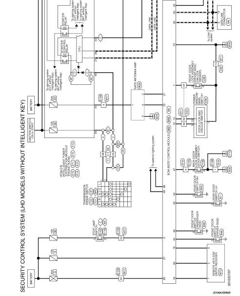
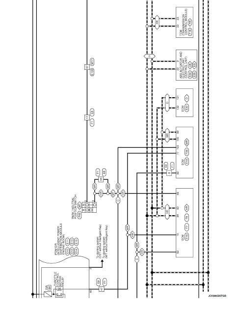
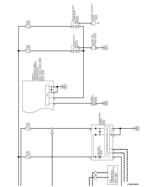
LHD
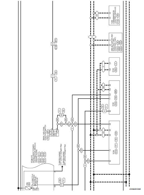
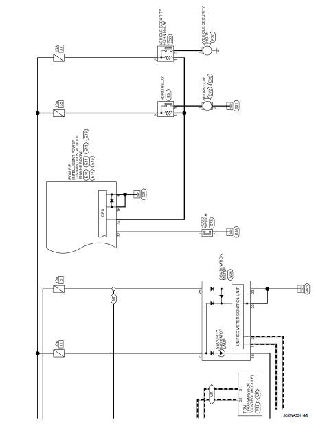
LHD : Wiring Diagram
For connector terminal arrangements, harness layouts, and alphabets in a
 (option abbreviation; if not
described in wiring diagram), refer to GI-12, "Connector Information/Explanation
of Option Abbreviation".
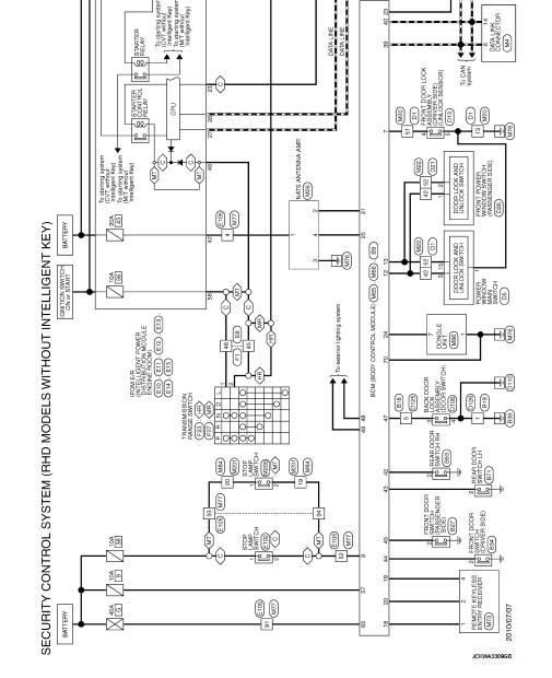
RHD
RHD : Wiring Diagram
For connector terminal arrangements, harness layouts, and alphabets in a
 (option abbreviation; if not
described in wiring diagram), refer to GI-12, "Connector Information/Explanation
of Option Abbreviation".
 ECU diagnosis information
ECM, BCM
List of ECU Reference
...
 Basic inspection
...
Other materials:
How to use the setup button
When the SETUP button is pushed, the Setup screen will appear on the display.
You can select and/or adjust several functions, features and modes that are available
for your vehicle.
Audio setup
Select the “Audio” key to adjust the following items to the preferred setting.
These setti ...
Conventional (fixed speed) cruise control mode
The conventional (fixed speed) cruise control mode in your Nissan Leaf offers a traditional driving experience, allowing you to maintain a constant speed between 25 and 90 mph (40 to 144 km/h) without the need to keep your foot engaged on the accelerator pedal.
WARNING
Unlike the ...
System
METER SYSTEM
METER SYSTEM : System Diagram
*: K9K engine models
METER SYSTEM : System Description
COMBINATION METER
• The combination meter receives necessary signals from each unit, switch,
and sensor to control the following
functions.
- Measuring instruments
- Shift position indic ...
