Nissan Juke Service and Repair Manual : System
METER SYSTEM
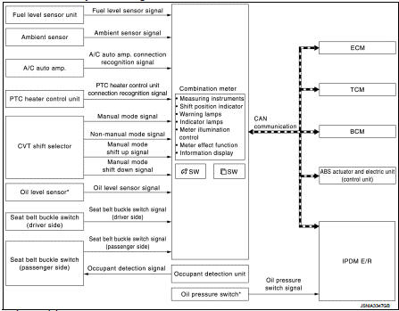
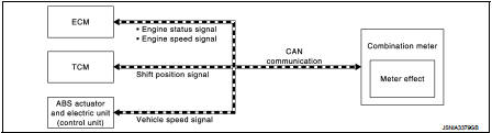
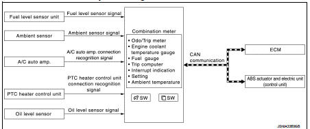
METER SYSTEM : System Diagram
*: K9K engine models
METER SYSTEM : System Description
COMBINATION METER
• The combination meter receives necessary signals from each unit, switch, and sensor to control the following functions.
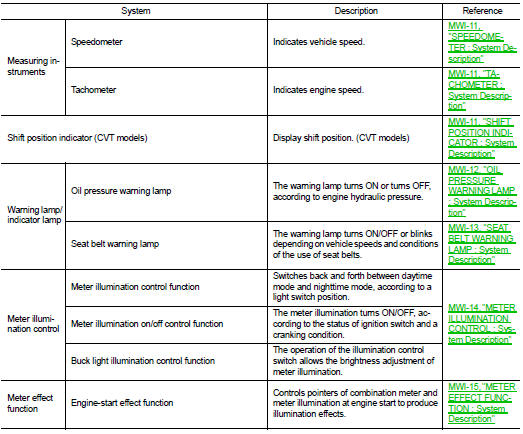
- Measuring instruments
- Shift position indicator
- Warning lamps
- Indicator lamps
- Meter illumination control
- Meter effect function
- Information display
• The combination meter incorporates a buzzer function that sounds an audible alarm with the integrated buzzer device. Refer to WCS-5, "Combination Meter" for further details.
• The combination meter includes an on board diagnosis function.
• The combination meter can be diagnosed with CONSULT-III.
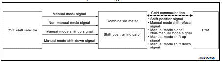
METER CONTROL FUNCTION LIST
ARRANGEMENT OF COMBINATION METER
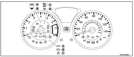
A. MR16DDT engine models with manual
mode CVT
B. K9K engine models
C. RHD models with CVT
METER SYSTEM : Fail-Safe
FAIL-SAFE
The combination meter activates the fail-safe control if CAN communication with each unit is malfunctioning.
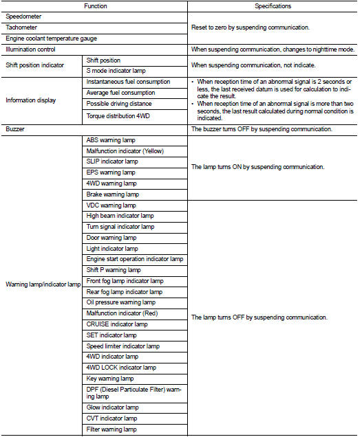
Speedometer
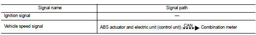
SPEEDOMETER : System Diagram
SPEEDOMETER : System Description
• The ABS actuator and electric unit (control unit) converts the rectangular wave signal provided by the wheel sensor to a vehicle speed signal and transmits it to the combination meter via CAN communication.
• The combination meter indicates the vehicle speed to the speedometer according to the vehicle speed signal received via CAN communication.
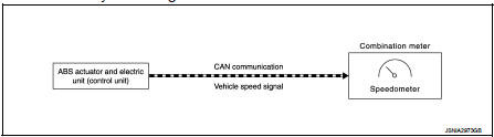
Tachometer
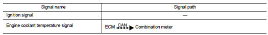
TACHOMETER : System Diagram
TACHOMETER : System Description
• ECM converts the pulse signal provided by the crankshaft position sensor to an engine speed signal and transmits it to the combination meter via CAN communication.
• The combination meter indicates the engine speed to the tachometer according to the engine speed signal received via CAN communication.
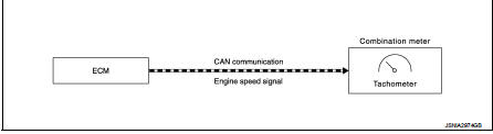
Shift position indicator
SHIFT POSITION INDICATOR : System Diag
SHIFT POSITION INDICATOR : System Description
The combination meter receives the shift position signal from TCM via CAN communication, and displays the shift position to the shift position indicator.
WITH MANUAL MODE
Manual Mode
• The combination meter receives the manual mode signal, non-manual mode signal,
manual mode shift up
signal, and manual mode shift down signal from CVT shift selector and transmits
them to TCM via CAN communication.
• TCM recognizes the manual mode operation status according to the manual mode signal, non-manual mode signal, manual mode shift up signal, and manual mode shift down signal received via CAN communication and transmits the manual mode indicator signal to the combination meter via CAN communication.
• The combination meter indicates shift position according to the manual mode indicator signal received via CAN communication.
Non-manual Mode
• TCM transmits the shift position signal to the combination meter via CAN
communication.
• The combination meter indicates shift position according to the shift position signal received via CAN communication.
Shift refusal warning and alarm • TCM sends a manual mode shift refusal signal to the combination meter via CAN communication when shiftup and shift-down can not be operated in manual mode.
• The combination meter blinks the shift position indicator and sounds a buzzer according to a manual mode shift refusal signal received via CAN communication.
WITHOUT MANUAL MODE
• TCM transmits the shift position signal to the combination meter via CAN communication.
• The combination meter indicates shift position according to the shift position signal received via CAN communication.
Oil pressure warning lamp
OIL PRESSURE WARNING LAMP : System Diagram
K9K ENGINE MODE
EXCEPT FOR K9K ENGINE MODELS
OIL PRESSURE WARNING LAMP : System Description
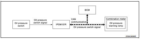
K9K ENGINE MODELS
• IPDM E/R reads the ON/OFF signals from the oil pressure switch and transmits the oil pressure switch signal to the combination meter via BCM with the CAN communication.
• The combination meter turns the oil pressure warning lamp ON (at the time of a reduction in hydraulic pressure)/ OFF (except at the time of a reduction in hydraulic pressure) according to the oil pressure switch signal received via CAN communication.
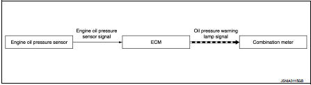
EXCEPT FOR K9K ENGINE MODELS
The combination meter turns the oil pressure warning lamp ON when receiving ECM to the oil pressure switch signal via CAN communication. For details, refer to EC-41, "Engine Oil Pressure Sensor" (MR16DDT) or EC- 462, "Engine Oil Pressure Sensor" (HR16DE).
Seat belt warning lamp
SEAT BELT WARNING LAMP : System Diagram
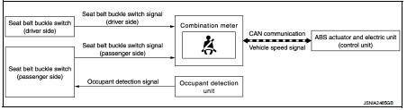
SEAT BELT WARNING LAMP : System Description
• The combination meter turns ON the seat belt warning lamp when the following operating conditions are satisfied.
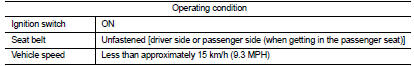
• The combination meter blinks the seat belt warning lamp when the following operating conditions are satisfied.
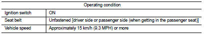
• The combination meter turns OFF the seat belt warning lamp when any of the following cancel condition is satisfied
NOTE
:
If cancel conditions are not satisfied, the seat belt warning lamp continues
blinking even when a vehicle
speed becomes less than approximately 15 km/h (9.3 MPH).
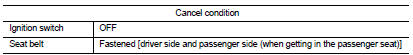
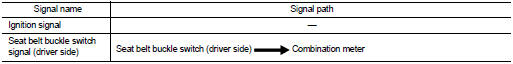
SIGNAL PATH
The combination meter receives the following signals to control seat belt warning lamp.
Meter illumination control
METER ILLUMINATION CONTROL : System Diagram
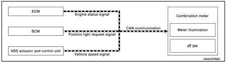
METER ILLUMINATION CONTROL : System Description
METER ILLUMINATION CONTROL FUNCTION
• Combination meter controls meter illumination, based on the following signal.
- Position light request signal • The combination meter switches mode between Daytime mode and Nighttime mode, according to the following conditions.
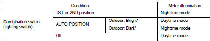
*: For further information, refer to INL-9, "ILLUMINATION CONTROL SYSTEM : System Description".
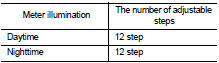
BUCK LIGHT ILLUMINATION CONTROL FUNCTION
The operation of the illumination control switch allows the brightness adjustment of meter illumination.
METER ILLUMINATION ON/OFF CONTROL FUNCTION
• Combination meter turns ON meter illumination when the following condition
is satisfied:
- Ignition switch ON
• Combination meter turns OFF meter illumination when any of the following
condition is satisfied:
- During a crank with vehicle speed less than 1 km/h (0.6 MPH) and ACC power
supply OFF
- Ignition switch OFF or ACC power supply OFF
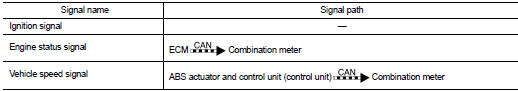
• The combination meter receives the following signals to control meter illumination

Meter effect function
METER EFFECT FUNCTION : System Diagram
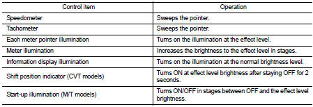
METER EFFECT FUNCTION : System Description
ENGINE-START EFFECT FUNCTION
When recognizing an engine start, the combination meter controls the following items for producing the effect.
• Speedometer
• Tachometer
• Each meter pointer illumination
• Meter illumination
• Information display illumination
• Shift position indicator (CVT models)
• Start-up illumination (M/T models)
Meter and Illumination Operations During Engine-start Effect The combination meter controls the following items during the engine-start effect.
NOTE
:
The pointers are stopped and illumination is turned off while cranking the
engine.
Engine Start Judgement The combination meter judges “engine-start” and activates the engine-start effect only once when the following operational conditions are all satisfied.
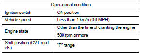
NOTE
:
ENGINE-START EFFECT exits when any of the above operational conditions is
cancelled during the enginestart
effect.
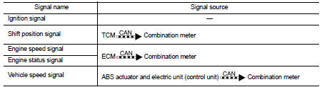
Signal Path
The combination meter judges “engine-start”, according to the following signals
and activates the engine-start
effect function.
NOTE
:
The engine-start effect function ends if any one of the above conditions is lost
during the activation of this function.
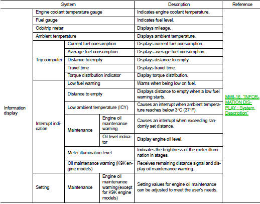
Information display
INFORMATION DISPLAY : System Diagram
INFORMATION DISPLAY : System Description
DESCRIPTION
• The combination meter receives signals necessary for controlling the operation of the information display from each unit, sensor and switch.
• The combination meter incorporates a trip computer that displays the warning/information according to the information received from each unit, sensor and switch.
• The combination meter shows the following functions on the information display.
- Odo/trip meter
- Engine coolant temperature gauge
- Fuel gauge
- Trip computer
- Interrupt indication
- Setting
- Ambient temperature
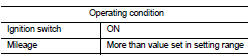
ODO/TRIP METER
The combination meter calculates mileage, based on the following signals and displays the mileage on the information display.
ENGINE COOLANT TEMPERATURE GAUGE
• ECM reads the engine coolant temperature signal from the engine coolant temperature sensor and transmits the signal to the combination meter via CAN communication.
• The combination meter indicates the engine coolant temperature to the water temperature gauge according to the engine coolant temperature signal received via CAN communication.
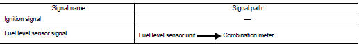
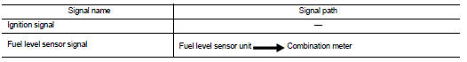
FUEL GAUGE
Control Outline
The combination meter reads the fuel level sensor signal from the fuel level
sensor unit and indicates the fuel
level to the fuel gauge.
Refuel Control
The unit judges that the driver is refueling the vehicle and accelerates the
fuel gauge segment movement if the
fuel level changes by 15  (3 - 1/4
lmp gal) or more.
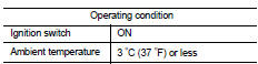
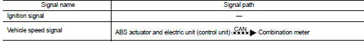
AMBIENT TEMPERATURE
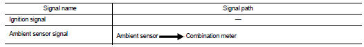
The combination meter calculates ambient temperature based on the following signals, and the calculated value is displayed on the information display.
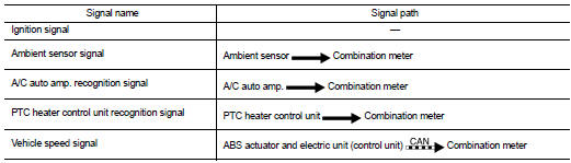
NOTE
:
• The indicated temperature is corrected based on an ignition signal, ambient
temperature detected by the
ambient sensor, and vehicle speed signal. The indicated temperature is not
raised under vehicle speed less
than 20 km/h (12 MPH).
• The ambient sensor input value that is displayed on “Data Monitor” of CONSULT-III is the value before the correction. It may not match the indicated temperature on the information display.
• Depending on engine heat or heat on the road surfaces, an ambient temperature may be indicated higher than actual one.
TRIP COMPUTER
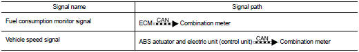
Current Fuel Consumption The combination meter calculates current fuel consumption based on the following signals, and the calculated value is displayed on the information display.
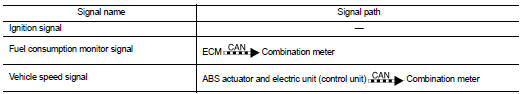
NOTE
:
• Current fuel consumption on the information display is updated approximately
every 0.5 seconds.
• Current fuel consumption on the information display shows 0 l/100km (0 mpg) when vehicle speed is 0 km/h (0 MPH).
Average Fuel Consumption The combination meter calculates average fuel consumption based on the following signals, and the calculated value is displayed on the information display.
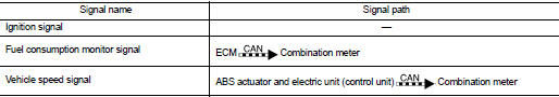
NOTE
:
• Average fuel consumption on the information display is updated approximately
every 30 seconds.
• Soon after a reset or when the ignition switch is turned ON right after battery removal and installation, “−−−” is displayed until after a travel of 30 seconds and approximately 500 m (0.31 mile).
Distance to Empty
The combination meter calculates distance to empty based on the following
signals, and the calculated value
is displayed on the information display.
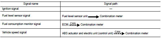
NOTE
:
• Distance to empty on the information display is updated approximately every 30
seconds.
• When the ignition switch is turned ON right after battery removal and installation, “−−−” is displayed until after a travel of 30 seconds.
• The indicated values may not match each other when refueling with the ignition switch ON.
Travel Time
The combination meter measures and displays travel time (ignition switch ON
time).
Torque Distribution Indicator Refer to DLN-18, "4WD SYSTEM : Torque Split Control".
INTERRUPT INDICATION
• The combination meter displays an interrupt regarding a warning, alert, and maintenance on the information display, based on signals received from each unit and switch.
• When conditions are satisfied, the normal screen switches to a warning screen to display an interrupt.
Meter Illumination Level The combination meter displays the illuminance level of the back light on the information display by turning the meter control switch.
ICY Warning (low ambient air temperature) • When the following operating condition is satisfied, the combination meter displays an ICY warning on the information display.
• The combination meter judges showing/hiding of “low ambient temperature”, according to the signals below:
Low Fuel Warning
• When all the following operating conditions are satisfied, the combination
meter displays a low fuel warning
on the information display by an interrupt.
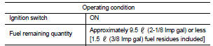
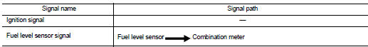
• The combination meter judges showing/hiding of “low fuel warning”, according to the signals below:
Distance to Empty
The combination meter calculates distance to empty based on the following
signals, and the calculated value
is displayed on the information display.
NOTE
:
• Distance to empty on the information display is updated approximately every 30
seconds.
• When the ignition switch is turned ON right after battery removal and installation, “−−−” is displayed until after a travel of 30 seconds.
• The indicated values may not match each other when refueling with the ignition switch ON.
Oil level Indicator
The combination meter reads a resistance value of the oil level sensor when the
following steps are completed
and displays the oil level sensor indicator when the ignition switch is turned
ON.
1. Ignition switch OFF
2. After a lapse of five minutes or more
3. The door on the front side is opened.
Oil Maintenance Warning (Except For K9K Engine Models) • When all the following operating conditions are satisfied, the combination meter displays wrench symbol and distance to oil change information on the information display by an interrupt.
• The combination meter judges showing/hiding of “engine oil warning”, according to the signals below:
Oil Maintenance Warning (K9K Engine Models) • The combination meter receives remaining distance signal from the ECM with CAN communication line.
• The combination meter indicates oil change remaining distance when receiving remaining distance signal.
• The combination meter indicates oil maintenance warning judged with the remaining distance signal received from the ECM.
For details, refer to EC section.
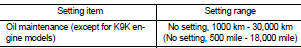
SETTING
Oil maintenance warning indication timing can be set.
Maintenance
Setting values for engine oil maintenance can be adjusted to meet the user's
needs.
 Component parts
Meter system
METER SYSTEM : Component Parts Location
1. Fuel level sensor unit (main)
2. Front seat belt buckle switch (passenger
side)
3. CVT shift selector assembly
Refer to TM-131, "C ...
 Operation
Switch Name and Function
...
Other materials:
NISSAN Advanced Air Bag System (front seats)
1. Crash zone sensor
2. Supplemental front-impact air bag modules
3. Front seat-mounted side-impact supplemental air bag modules
4. Occupant classification sensors (weight sensors)
5. Occupant classification system control unit
6. Roof-mounted curtain side-impact supplemental air bag inflator ...
System
EPS system : System Description
• EPS control unit performs an arithmetical operation on data, such
as steering wheel turning force (sensor signal) from the torque
sensor, vehicle speed signal, etc. Then it generates an optimum
assist torque signal to the EPS motor according to the driving con ...
Meters and gauges
1. Tachometer
2. Engine coolant temperature gauge
3. Vehicle information display
— Odometer/twin trip odometer
— Trip computer
— Torque vectoring AWD (AWD model)
— Outside air temperature
4. Fuel gauge
5. Speedometer
6. Warning/indicator lights
7. Instrument brightness control kn ...
