Nissan Juke Service and Repair Manual : Component parts
Meter system
METER SYSTEM : Component Parts Location
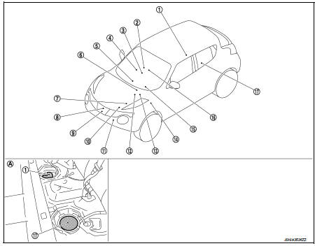
1. Fuel level sensor unit (main)
2. Front seat belt buckle switch (passenger
side)
3. CVT shift selector assembly
Refer to TM-131, "CVT CONTROL
SYSTEM : Component Parts Location"
(MR16DDT engine models).
Refer to TM-314, "CVT CONTROL SYSTEM : Component Parts Location" (HR16DE engine models).
4. Occupant detection unit (Under the passenger seat cushion pad) 5. A/C auto amp.
Refer to HAC-12, "Component Parts Location" (4WD models).
Refer to HAC-103, "AUTOMATIC AIR CONDITIONING SYSTEM : Component Parts Location" (2WD models).
6. ECM Refer to EC-455, "ENGINE CONTROL SYSTEM : Component Parts Location" (HR16DE engine models).
Refer to EC-813, "Component Parts Location" (K9K engine models).
7. IPDM E/R Refer to PCS-5, "Component Parts Location" (with I-KEY).
Refer to PCS-37, "Component Parts Location" (without I-KEY).
8. Oil pressure switch Refer to EM-103, "Exploded View" (MR16DDT engine models).
Refer to EM-227, "Exploded View" (HR16DE engine models).
Refer to LU-37, "Exploded View" (K9K engine models).
9. Oil level sensor Refer to EM-99, "Exploded View" (MR16DDT engine models).
Refer to EM-222, "Exploded View" (HR16DE engine models).
Refer to EM-330, "Disassembly and Assembly" (K9K engine models).
10. ECM Refer to EC-25, "ENGINE CONTROL SYSTEM : Component Parts Location" (MR16DDT engine models).
11. Ambient sensor Refer to HAC-12, "Component Parts Location" (2WD models).
Refer to HAC-103, "AUTOMATIC AIR CONDITIONING SYSTEM : Component Parts Location" (4WD models).
12. ABS actuator and electric unit (control unit) Refer to BRC-97, "Component Parts Location" (with ESP).
Refer to BRC-9, "Component Parts Location" (without ESP).
13. TCM
Refer to TM-131, "CVT CONTROL
SYSTEM : Component Parts Location"
(for RE0F10B models)
Refer to TM-314, "CVT CONTROL
SYSTEM : Component Parts Location"
(for RE0F11A models)
14. BCM
Refer to BCS-6, "BODY CONTROL
SYSTEM : Component Parts Location"
(with intelligent key system)
Refer to BCS-96, "BODY CONTROL
SYSTEM : Component Parts Location"
(without intelligent key system)
15. Combination meter
16. Front seat belt buckle switch (driver
side)
17. Fuel level sensor unit (sub)
A. Rear seat (bottom)
METER SYSTEM : Component Description

 System
METER SYSTEM
METER SYSTEM : System Diagram
*: K9K engine models
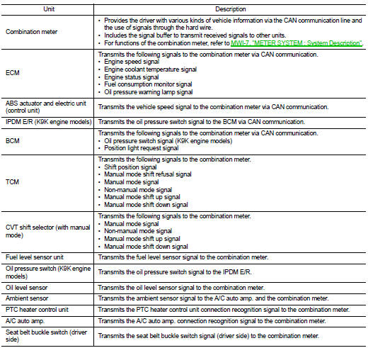
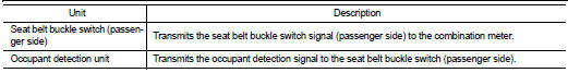
METER SYSTEM : System Description
COMBINATION METER
• The combination meter receives necessary signals from each unit, switch, ...
Other materials:
Precaution for Supplemental Restraint System (SRS) "AIR BAG" and "SEAT BELT
PRE-TENSIONER"
The Supplemental Restraint System such as “AIR BAG” and “SEAT BELT PRE-TENSIONER”,
used along
with a front seat belt, helps to reduce the risk or severity of injury to the
driver and front passenger for certain
types of collision. Information necessary to service the system safely is
...
ABS warning lamp
Component Function Check
1.CHECK ABS WARNING LAMP FUNCTION
Check that ABS warning lamp in combination meter turns ON for approx. 1
second after ignition switch is
turned ON.
CAUTION:
Never start engine.
Is the inspection result normal?
YES >> INSPECTION END
NO >> Proceed to B ...
P2135 TP sensor
DTC Logic
DTC DETECTION LOGIC
NOTE:
If DTC P2135 is displayed with DTC P0643, first perform the trouble diagnosis
for DTC P0643. Refer to
EC-307, "DTC Logic".
DTC CONFIRMATION PROCEDURE
1.PRECONDITIONING
If DTC Confirmation Procedure has been previously conducted, always perform ...
