Nissan Juke Service and Repair Manual : Coil spring
Exploded View
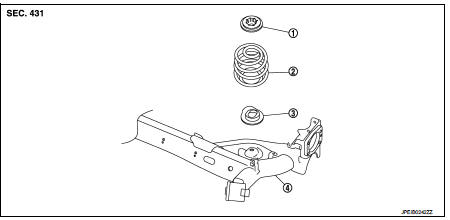
1. Upper rubber seat
2. Coil spring
3. Lower rubber seat
4. Rear suspension beam
Removal and Installation
REMOVAL
1. Remove tires. Refer to WT-7, "Removal and Installation".
2. Set jack under rear suspension beam.
CAUTION:
• Never damage the suspension beam with a jack.
• Check the stable condition when using a ja
ck.
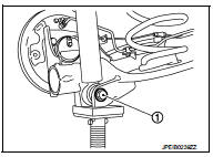
3. Remove rear shock absorber mounting bolts (lower side). Refer to RSU-8, "Exploded View".
4. Slowly lower jack, then remove upper rubber seat, coil spring and lower rubber seat from rear suspension beam.
CAUTION:
Operate while checking that jack supporting status is stable.
5. Perform inspection after removal. Refer to RSU-12, "Inspection".
INSTALLATION
Note the following, and install in the reverse order of removal.
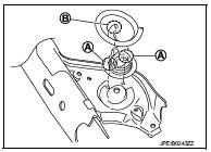
• Install lower rubber seat with its protrusion (A) on the lower area aligned with the hole of rear suspension beam.
• Securely install coil spring with the lower end (B) of the major diameter aligned with the steps of lower rubber seat.
• Perform inspection after installation. Refer to RSU-12, "Inspection".
Inspection
INSPECTION AFTER REMOVAL
Check lubber seat and coil spring for deformation, crack, and damage. Replace it if necessary.
INSPECTION AFTER INSTALLATION
Check wheel alignment. Refer to RSU-6, "Inspection".
 Rear shock absorber
Exploded View
1. Rear suspension beam
2. Shock absorber
3. Bound bumper
4. Bound bumper cover
5. Washer
6. Bushing
7. Distance tube
8. Piston rod lock nut
9. Cap
: Always replace aft ...
 Rear suspension beam
Exploded View
1. Rear suspension beam
2. Rear suspension arm bracket
: Always replace after every
disassembly.
: N·m (kg-m, ft-lb)
Removal and Installation
REMOVAL
1. Remove tires. Refer ...
Other materials:
Anti-hijack function does not operate
Diagnosis Procedure
1.CHECK “DOOR LOCK–UNLOCK SET” SETTING IN “WORK SUPPORT”
1. Select “DOOR LOCK” of “BCM” using CONSULT-III.
2. Select “DOOR LOCK-UNLOCK SET” in “WORK SUPPORT” mode.
3. Check “DOOR LOCK-UNLOCK SET” in “WORK SUPPORT”
Refer to DLK-41, "DOOR ...
B1068, B1073 passenger air bag module
DTC Logic
DTC DETECTION LOGIC
DTC CONFIRMATION PROCEDURE
1.CHECK SELF-DIAG RESULT
With CONSULT-III
1. Turn ignition switch ON.
2. Perform “Self Diagnostic Result” mode of “AIR BAG” using CONSULT-III.
Without CONSULT-III
1. Turn ignition switch ON.
2. Check the air bag warning la ...
Removal and Installation Procedure for CVT Unit Connector
REMOVAL
• Rotate bayonet ring (A) counterclockwise. Pull out CVT unit harness
connector (B) upward and remove it.
INSTALLATION
1. Align marking (A) on CVT unit harness connector terminal with
marking (B) on bayonet ring. Insert CVT unit harness connector.
2. Rotate bayonet ring clockwise.
...
