Nissan Juke Service and Repair Manual : Outside key antennA
Driver side
DRIVER SIDE : Removal and Installation
REMOVAL
Remove the driver side outside handle. Refer to DLK-339, "OUTSIDE HANDLE : Removal and Installation".
INSTALLATION
Install in the reverse order of removal.
Passenger side
PASSENGER SIDE : Removal and Installation
REMOVAL
Remove the passenger side outside handle. Refer to DLK-339, "OUTSIDE HANDLE : Removal and Installation".
INSTALLATION
Install in the reverse order of removal.
Rear bumper
REAR BUMPER : Removal and Installation
REMOVAL
1. Remove the rear bumper fascia. Refer to EXT-16, "Removal and Installation".
2. Remove the outside key antenna (rear bumper) (1) mounting clip (A), then remove outside key antenna (rear bumper).
INSTALLATION
Install in the reverse order of removal.
 Inside key antenna
Instrument center
INSTRUMENT CENTER : Removal and Installation
REMOVAL
1. Remove the multi display unit. Refer to AV-125, "Removal and
Installation".
2. Remove the inside key antenna ( ...
 Intelligent key warning buzzer
Removal and Installation
REMOVAL
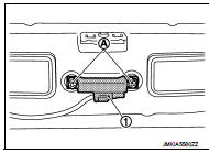
1. Remove the Intelligent Key warning buzzer (1) mounting bolt
(A), and then remove the Intelligent Key warning buzzer.
INSTALLATION
Install in the reverse orde ...
Other materials:
Glow plug
Exploded View
1. Glow plug
Engine front
: N·m (kg-m, ft-lb)
Removal and Installation
REMOVAL
CAUTION:
Remove glow plug only if necessary. If carbon adheres, it may be stuck and
broken.
1. Disconnect the battery cable from the negative terminal.
2. Remove cowl top extension. Refer to E ...
Transfer case
Exploded View
1. Pinion lock nut
2. Companion flange
3. Drive pion oil seal
4. Pinon rear bearing
5. Transfer case
6. Gasket
7. Filler plug
8. Collapsible spacer
9. Drive pinion adjust shim
10. Drive pinion
11. Pinion front bearing
12. Ring gear
13. Ring gear shaft
14. Ring ...
P1226 TP sensor
DTC Logic
DTC DETECTION LOGIC
DTC CONFIRMATION PROCEDURE
1.PRECONDITIONING
If DTC Confirmation Procedure has been previously conducted, always turn
ignition switch OFF and wait at
least 10 seconds before conducting the next test.
TESTING CONDITION:
Before performing the following proced ...
