Nissan Juke Service and Repair Manual : Inside key antenna
Instrument center
INSTRUMENT CENTER : Removal and Installation
REMOVAL
1. Remove the multi display unit. Refer to AV-125, "Removal and Installation".
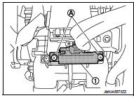
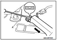
2. Remove the inside key antenna (instrument center) (1) mounting clip (A), and then remove inside key antenna (instrument center).
CAUTION:
Be careful not to drop mounting clip (A) into instrument
panel.
INSTALLATION
Install in the reverse order of removal.
Console
CONSOLE : Removal and Installation
REMOVAL
1. Remove the center console assembly. Refer to IP-23, "Removal and Installation".
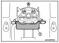
2. Remove the inside key antenna (console) (1) mounting clip (A), and then remove inside key antenna (console).
INSTALLATION
Install in the reverse order of remova
Luggage room
LUGGAGE ROOM : Exploded View
1. Inside key antenna (luggage room) 2. Clip
 : Do not reuse
LUGGAGE ROOM : Removal and Installation
REMOVAL
1. Remove the luggage floor finisher. Refer to INT-29, "Exploded View".
2. Remove the inside key antenna (luggage room) (1) mounting clip RH (A).
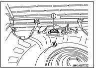
3. Disengage inside key antenna (luggage room) fixing clip using a flat-bladed screwdriver (A), and then pull out forward the inside key antenna (luggage room).
INSTALLATION
Install in the reverse order of removal.
CAUTION:
Visually check the clips for deformation and damage during installation.
Replace with new ones if necessary.
 Door switch
Exploded View
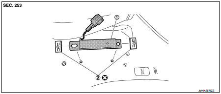
1. Door switch
2. TORX bolt
Removal and Installation
REMOVAL
Remove the TORX bolt (A), and then remove door switch (1).
INSTALLATION
Install in the reverse order of removal. ...
 Outside key antennA
Driver side
DRIVER SIDE : Removal and Installation
REMOVAL
Remove the driver side outside handle. Refer to DLK-339, "OUTSIDE HANDLE :
Removal and Installation".
INSTALLATION
Install ...
Other materials:
Handling for Adhesive and Primer
• Never use an adhesive that is past its usable date. Shelf life of this
product is limited to six months after the
date of manufacture. Carefully adhere to the expiration or manufacture date
printed on the box.
• Keep primers and adhesive in a cool, dry place. Ideally, they should be stor ...
Precaution for Supplemental Restraint System (SRS) "AIR BAG" and "SEAT BELT
PRE-TENSIONER"
The Supplemental Restraint System such as “AIR BAG” and “SEAT BELT PRE-TENSIONER”,
used along
with a front seat belt, helps to reduce the risk or severity of injury to the
driver and front passenger for certain
types of collision. Information necessary to service the system safely is
...
Handling precaution
Nissan Dynamic Control System
• The engine torque, engine power, boost, and instantaneous fuel consumption
are provided for information
purposes only. They are not intended to prompt the driver to adjust driving
style. The readings may be
slightly delayed relative to the actual vehicle beha ...
