Nissan Juke Service and Repair Manual : Rear shock absorber
Exploded View
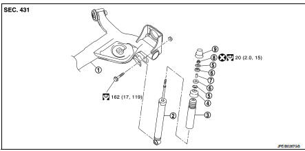
1. Rear suspension beam
2. Shock absorber
3. Bound bumper
4. Bound bumper cover
5. Washer
6. Bushing
7. Distance tube
8. Piston rod lock nut
9. Cap
 : Always replace after every
disassembly.
 : N┬Ęm (kg-m, ft-lb)
Removal and Installation
REMOVAL
1. Remove tires. Refer to WT-7, "Removal and Installation".
2. Set suitable jack under rear suspension beam.
CAUTION:
ŌĆó Never damage the suspension beam with a jack.
ŌĆó Check the stable condition when using a jack.
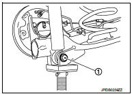
3. Remove shock absorber mounting bolt (lower side) (1).
4. Remove shock absorber mask. Refer to INT-29, "Exploded View".
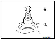
5. Remove cap.
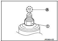
6. Remove piston rod lock nut (1), and then remove washer and bushing.
NOTE
:
To loosen piston rod lock nut, fix the tip (A) of the piston rod.
7. Remove shock absorber assembly.
8. Remove bushing, distance tube, bound bumper cover, and bound bumper from shock absorber.
9. Perform inspection after removal. Refer to RSU-10, "Inspection".
INSTALLATION
Note the following, and install in the reverse order of removal.
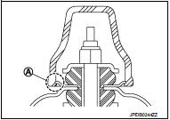
ŌĆó To install bushings (1), securely insert protrusion (A) into the hole on the vehicle body side.
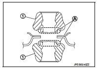
ŌĆó Install washer (1) in the direction shown in the figure.
 : Bushing side
ŌĆó Perform final tightening of bolts and nuts at the shock absorber lower side (rubber bushing), under unladen conditions with tires on level ground.
ŌĆó Hold a head (A) of shock absorber piston rod not to have it rotate, then tighten the piston rod lock nut (1) to the specified torque.
CAUTION:
Never reuse piston rod lock nut.
ŌĆó When installing the cap, securely engage the cap groove (A) with the flange on the vehicle side.
ŌĆó Perform inspection after installation. Refer to RSU-10, "Inspection".
ŌĆó After replacing the shock absorber, always follow the disposal procedure to discard the shock absorber. Refer to RSU-10, "Inspection".
Inspection
INSPECTION AFTER REMOVAL
Shock Absorber
Check the following items, and replace the part if necessary.
ŌĆó Shock absorber for deformation, cracks, and other damage.
ŌĆó Piston rod for damage, uneven wear, and distortion.
ŌĆó Oil leakage
Bound Bumper, Bushing
Check for cracks and damage. Replace it if necessary.
Washer, Bound Bumper Cover, Distance Tube ŌĆó Check for cracks and damage. Replace it if necessary.
INSPECTION AFTER INSTALLATION
Check wheel alignment. Refer to RSU-6, "Inspection".
Disposal
1. Set shock absorber horizontally to the ground with the piston rod fully extracted.
2. Drill 2 ŌĆō 3 mm (0.08 ŌĆō 0.12 in) hole at the position (
 ) from top
as shown in the figure to release gas gradually.
CAUTION:
ŌĆó Wear eye protection (safety glass).
ŌĆó Wear gloves.
ŌĆó Be careful with metal chips or oil blown out by the compressed gas.
NOTE:
ŌĆó Drill vertically in this direction (
 ).
).
ŌĆó Directly to the outer tube avoiding brackets.
ŌĆó The gas is clear, colorless, odorless, and harmless.
A : 20 ŌĆō 30 mm (0.79 ŌĆō 1.18 in)
3. Position the drilled hole downward and drain oil by moving the piston rod several times.
CAUTION: Dispose of drained oil according to the law and local regulations.

 Coil spring
Exploded View
1. Upper rubber seat
2. Coil spring
3. Lower rubber seat
4. Rear suspension beam
Removal and Installation
REMOVAL
1. Remove tires. Refer to WT-7, "Removal and Installatio ...
Other materials:
Spark plug
Removal and Installation
REMOVAL
1. Remove ignition coil. Refer to EM-178, "Exploded View".
2. Remove spark plug with a spark plug wrench (commercial service
tool).
a : 14 mm (0.55 in)
CAUTION:
Never drop or shock spark plug.
INSTALLATION
Install in the reverse order of removal ...
Vehicle Dynamic Control (VDC) system
The Vehicle Dynamic Control (VDC) system in your Nissan Leaf serves as a comprehensive safety net, utilizing an array of sophisticated sensors to continuously monitor driver inputs, such as steering and braking, alongside the actual motion and attitude of the vehicle.
Under challengin ...
C1115 wheel sensor
DTC Logic
DTC CONFIRMATION PROCEDURE
1.PRECONDITIONING
If ŌĆ£DTC CONFIRMATION PROCEDUREŌĆØ has been previously conducted, always turn
ignition switch OFF and
wait at least 10 seconds before conducting the next test.
>> GO TO 2.
2.CHECK DTC DETECTION
With CONSULT-III.
1. Stat th ...
