Nissan Juke Service and Repair Manual : P2127, P2128 APP sensor
DTC Logic
DTC DETECTION LOGIC
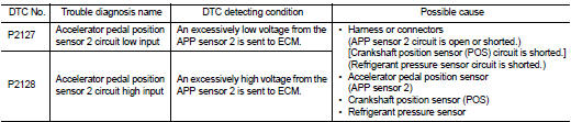
DTC CONFIRMATION PROCEDURE
1.PRECONDITIONING
If DTC Confirmation Procedure has been previously conducted, always turn ignition switch OFF and wait at least 10 seconds before conducting the next test.
TESTING CONDITION:
Before performing the following procedure, confirm that battery voltage is more
than 10 V at idle.
>> GO TO 2.
2.PERFORM DTC CONFIRMATION PROCEDURE
1. Start engine and let it idle for 1 second.
2. Check DTC.
Is DTC detected? YES >> Go to EC-751, "Diagnosis Procedure".
NO >> INSPECTION END
Diagnosis Procedure
1.CHECK GROUND CONNECTION
1. Turn ignition switch OFF.
2. Check ground connection E38. Refer to Ground Inspection in GI-44, "Circuit Inspection".
Is the inspection result normal? YES >> GO TO 2.
NO >> Repair or replace ground connection.
2.CHECK APP SENSOR 2 POWER SUPPLY CIRCUIT-I
1. Disconnect accelerator pedal position (APP) sensor harness connector.
2. Turn ignition switch ON.
3. Check the voltage between APP sensor harness connector and ground.
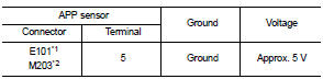
*1: LHD models or RHD models with CVT *2: RHD models with M/T
Is the inspection result normal? YES >> GO TO 6.
NO >> GO TO 3.
3.CHECK APP SENSOR 2 POWER SUPPLY CIRCUIT-II
1. Turn ignition switch OFF.
2. Disconnect ECM harness connector.
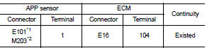
3. Check the continuity between APP sensor harness connector and ECM harness connector.
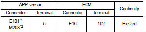
*1: LHD models or RHD models with CVT *2: RHD models with M/T
Is the inspection result normal? YES >> GO TO 4.
NO >> Repair open circuit or short to ground or short to power in harness or connectors.
4.CHECK SENSOR POWER SUPPLY CIRCUIT
Check harness for short to power and short to ground, between the following terminals.
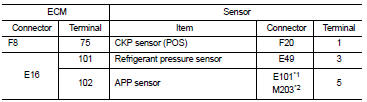
*1: LHD models or RHD models with CVT *2: RHD models with M/T
Is the inspection result normal? YES >> GO TO 5.
NO >> Repair short to ground or short to power in harness or connectors.
5.CHECK COMPONENTS
Check the following.
• Crankshaft position sensor (POS) (Refer to EC-658, "Component Inspection".) • Refrigerant pressure sensor (Refer to EC-790, "Diagnosis Procedure".)
Is the inspection result normal? YES >> GO TO 10.
NO >> Replace malfunctioning component.
6.CHECK APP SENSOR 2 GROUND CIRCUIT FOR OPEN AND SHORT
1. Turn ignition switch OFF.
2. Disconnect ECM harness connector.
3. Check the continuity between APP sensor harness connector and ECM harness connector.
*1: LHD models or RHD models with CVT *2: RHD models with M/T
4. Also check harness for short to ground and short to power.
Is the inspection result normal? YES >> GO TO 7.
NO >> Repair open circuit or short to ground or short to power in harness or connectors.
7.CHECK APP SENSOR 2 INPUT SIGNAL CIRCUIT FOR OPEN AND SHORT
1. Check the continuity between APP sensor harness connector and ECM harness connector.
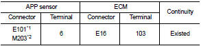
*1: LHD models or RHD models with CVT *2: RHD models with M/T
2. Also check harness for short to ground and short to power.
Is the inspection result normal? YES >> GO TO 8.
NO >> Repair open circuit or short to ground or short to power in harness or connectors.
8.CHECK APP SENSOR
Refer to EC-753, "Component Inspection".
Is the inspection result normal? YES >> GO TO 10.
NO >> GO TO 9.
9.REPLACE ACCELERATOR PEDAL ASSEMBLY
Replace accelerator pedal assembly. Refer to ACC-3, "Exploded View".
>> INSPECTION END
10.CHECK INTERMITTENT INCIDENT
Refer to GI-42, "Intermittent Incident".
>> INSPECTION END
Component Inspection
1.CHECK ACCELERATOR PEDAL POSITION SENSOR
1. Reconnect all harness connectors disconnected.
2. Turn ignition switch ON.
3. Check the voltage between ECM harness connector and ground.
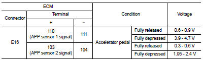
Is the inspection result normal? YES >> INSPECTION END
NO >> GO TO 2.
2.REPLACE ACCELERATOR PEDAL ASSEMBLY
Replace accelerator pedal assembly. Refer to ACC-3, "Exploded View".
>> INSPECTION END
 P2122, P2123 APP sensor
DTC Logic
DTC DETECTION LOGIC
NOTE:
If DTC P2122 or P2123 is displayed with DTC P0643, first perform the trouble
diagnosis for DTC P0643.
Refer to EC-686, "DTC Logic".
DTC CONFIRM ...
 P2135 TP sensor
DTC Logic
DTC DETECTION LOGIC
NOTE:
If DTC P2135 is displayed with DTC P0643, first perform the trouble diagnosis
for DTC P0643. Refer to
EC-686, "DTC Logic".
DTC CONFIRMATION PROCE ...
Other materials:
B1215, B1216, B1217 satellite sensor LH
DTC Logic
DTC DETECTION LOGIC
DTC CONFIRMATION PROCEDURE
1.CHECK SELF-DIAG RESULT
With CONSULT-III
1. Turn ignition switch ON.
2. Perform “Self Diagnostic Result” mode of “AIR BAG” using CONSULT-III.
Without CONSULT-III
1. Turn ignition switch ON.
2. Check the air bag warning la ...
Wiring diagram
Engine control system
For connector terminal arrangements, harness layouts, and alphabets in a
(option abbreviation; if not
described in wiring diagram), refer to GI-12, "Connector Information/Explanation
of Option Abbreviation".
...
Speaker Adaptation (SA) mode
Speaker Adaptation allows up to two out-of dialect users to train the system
to improve recognition accuracy. By repeating a number of commands, the users can
create a voice model of their own voice that is stored in the system.
The system is capable of storing a different speaker adaptation mo ...
