Nissan Juke Service and Repair Manual : Wiring diagram
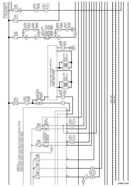
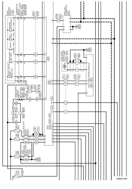
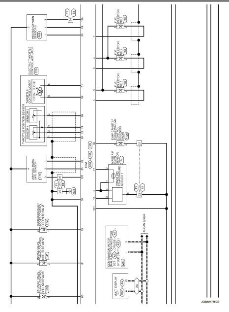
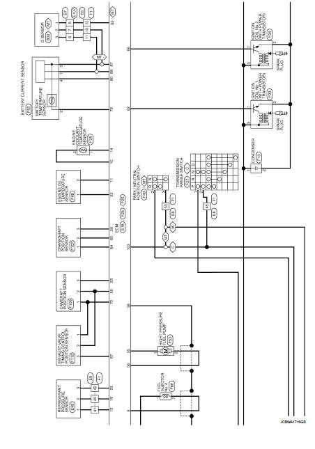
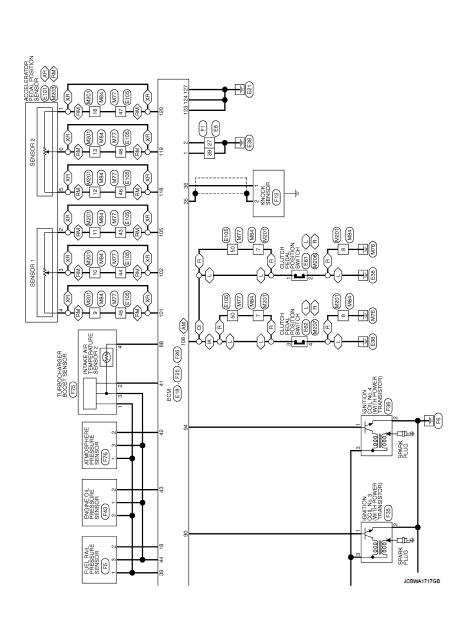
Engine control system
For connector terminal arrangements, harness layouts, and alphabets in a
 (option abbreviation; if not
described in wiring diagram), refer to GI-12, "Connector Information/Explanation
of Option Abbreviation".

 Test Value and Test Limit
The following is the information specified in Service $06 of ISO 15031-5.
The test value is a parameter used to determine whether a system/circuit
diagnostic test is OK or NG while
being monitor ...
 Basic inspection
...
Other materials:
General Precautions
WARNING:
When replacing fuel line parts, be sure to observe the following.
ŌĆó Put a ŌĆ£CAUTION: FLAMMABLEŌĆØ sign in the workshop.
ŌĆó Be sure to work in a well ventilated area and furnish workshop with a CO2 fire
extinguisher.
ŌĆó Never smoke while servicing fuel system. Keep open flames a ...
Refilling
1. Remove filler plug (1) and gasket from transaxle case.
2. Fill with new gear oil until oil level reaches the specified limit at
filler plug mounting hole as shown in the figure.
Oil grade and
viscosity
: Refer to MA-13, "Fluids and Lubricants".
Oil capacity : Refer to TM-63, " ...
P173B 1GR incorrect ratio
DTC Logic
DTC CONFIRMATION PROCEDURE
CAUTION:
ŌĆó Be sure to perform ŌĆ£TM-445, "Diagnosis Procedure"ŌĆØ and then perform ŌĆ£DTC
CONFIRMATION PROCEDUREŌĆØ.
ŌĆó Never perform "DTC CONFIRMATION PROCEDURE" before the repairs. Doing so may
result in a secondary
malfunction.
...
