Nissan Juke Service and Repair Manual : Control linkage
Exploded View
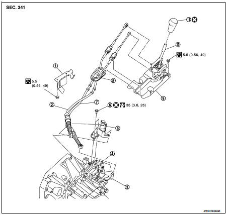
1. Bracket
2. Selector cable
3. Shifter lever A
4. Selector lever
5. Cable mounting bracket
6. Tapping bolt
7. Shifter cable
8. Grommet
9. M/T shift selector assembly
10. Shifter lever
11. Shifter lever knob
 : Always replace after every
disassembly.
 : N·m (kg-m, ft-lb)
 : N·m (kg-m, in-lb)
Removal and Installation
REMOVAL
1. Shift the shifter lever to the neutral position.
2. Remove air cleaner case. Refer to EM-161, "Removal and Installation".
3. Pull out and disconnect the each cable from the shifter lever A and the selector lever, using a suitable remover.
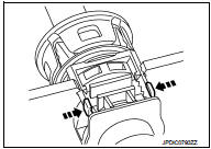
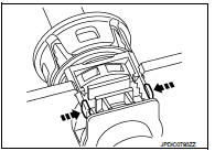
4. While pressing the lock of the selector cable in the direction of the arrow shown in the figure, remove the selector cable from the cable mounting bracket.
5. While pressing the lock of the shifter cable in the direction of the arrow shown in the figure, remove the shifter cable from the cable mounting bracket.
6. Remove cable mounting bracket from clutch housing.
7. Pull the shifter lever knob upward to remove.
8. Remove center console assembly. Refer to IP-23, "Removal and Installation".
9. Pull out and disconnect the each cable from the pin of the M/T shift selector assembly, using a suitable remover.
10. While pressing the lock of the selector cable in the direction of the arrow shown in the figure, remove the selector cable from the M/T shift selector assembly.
11. While pressing the lock of the shifter cable in the direction of the arrow shown in the figure, remove the shifter cable from the M/T shift selector assembly.
12. Remove the M/T shift selector assembly.
13. Remove exhaust front tube and heat plate. Refer to EX-12, "Removal and Installation".
14. Remove the bracket from the vehicle.
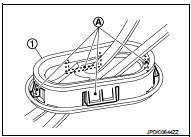
15. Disengage the pawls (A) of the grommet (1), and pull downwards to remove.
16. Remove the shifter cable and selector cable from the vehicle.
INSTALLATION
Note the following, and install in the reverse order of removal.
CAUTION:
• Install each cable without causing interference with other parts, a 120 mm
(4.72 in)-or-less bend, and
a 180-degrees-or-more twist.
• Install boot of each cable without causing interference with other parts and a 90-degrees-or-more twist.
• Fit boot of to center console assembly the groove on shifter lever knob.
• To install the shifter lever knob, press it into the shifter lever.
CAUTION:
• Never reuse shifter lever knob.
• Be careful with orientation of shifter lever knob.
• Tapping work for tapping bolts is not applied to new clutch housing. Do not perform tapping by other than screwing tapping bolts because tapping is formed by screwing tapping bolts into clutch housing.
CAUTION:
Never reuse tapping bolt.
• Insert the each cable until it reaches the cable mounting bracket and M/T shift selector assembly.
• Insert the each cable until it reaches the shifter lever A and the selector lever.
• Shift the shifter lever to the neutral position.
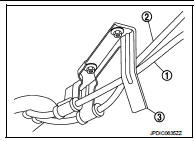
• Install the shifter cable (1) and the selector cable (2) to the bracket (3) as shown in the figure.
Inspection
INSPECTION AFTER INSTALLATION
Shifter Lever Knob
Check that the shifter lever knob is installed in the right position.
Shifter Cable and Selector Cable • Pull each cable in the removal direction to check that it dose not disconnect from the cable mounting bracket.
• Pull each cable in the removal direction to check that it dose not disconnect from the M/T shift selector assembly.
• Pull grommet in the removal direction to check that it dose not disconnect from the vehicle.
M/T Shift Selector Assembly and Shifter Lever • Check that there is no tangle, hook, abnormal sound, looseness, and interference when the shifter lever is moved to each position. If there is a malfunction, then repair or replace the malfunctioning part.
• Check that the shifter lever smoothly returns to the neutral position after moving the lever from 1st to 2nd gear and moving hands off the lever. If there is a malfunction, then repair or replace the malfunctioning part.
• Check that the shifter lever smoothly returns to the neutral position after moving the lever from 5th to the reverse gear position and moving hands off the lever. If there is a malfunction, then repair or replace the malfunctioning part.
 Position switch
Removal and Installation
REMOVAL
1. Drain gear oil. Refer to TM-22, "Draining".
2. Disconnect position switch connector (A).
3. Remove position switch from transaxle case.
INSTALLATIO ...
 Air breather hose
Exploded View
1. Clip
2. Air breather hose
3. 2 way connector
Removal and Installation
REMOVAL
1. Remove clips (1).
: Vehicle front
2. Remove air breather hose from the 2 way connector.
...
Other materials:
ABS actuator and electric unit (control unit)
Exploded View
LHD
MR16DDT (2WD), HR16DE
1. ABS actuator and electric unit (control
unit)
2. ABS actuator and electric unit (control
unit) harness connector
3. Bracket
A. To front LH caliper
B. To rear RH caliper
C. To rear LH caliper
D. To front RH caliper
E. To master cylinder seco ...
Front oil seal
Exploded View
1. Rear final drive assembly
2. Front oil seal
3. Companion flange
4. Companion flange lock nut
A. Oil seal lip
: Vehicle front
: N·m (kg-m, ft-lb)
: Never reuse parts
: Apply multi purpose grease
: Apply gear oil.
Removal and Installation
REMOVAL
CAUTION:
Verify ide ...
Clutch pedal
LHD : Exploded View
1. Clutch pedal
2. Stopper rubber
3. Clip
4. Clutch interlock switch *1
5. Clutch pedal position switch *2
6. Pedal pad
7. Pedal stopper rubber
*1 : With push-button ignition switch system
*2 : With ASCD or with push-button ignition switch system
: N·m (kg-m, ft- ...
