
Nissan Juke Service and Repair Manual : Position switch
Removal and Installation
REMOVAL
1. Drain gear oil. Refer to TM-22, "Draining".
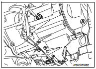
2. Disconnect position switch connector (A).
3. Remove position switch from transaxle case.
INSTALLATION
1. Apply recommended sealant to threads of position switch.
• Use Genuine Liquid Gasket, Three Bond 1215 or an equivalent.
CAUTION:
Remove old sealant and oil adhering to threads.
2. Install position switch to transaxle case.
3. Tighten position switch to the specified torque. Refer to TM-33, "Exploded View".
4. Refill gear oil. Refer to TM-22, "Refilling".
Inspection
INSPECTION AFTER INSTALLATION
• Check continuity between position switch terminals. Refer to TM-20, "BACK-UP LAMP SWITCH : Component Inspection" (Back-up lamp switch) and TM-20, "PARK/NEUTRAL POSITION (PNP) SWITCH : Component Inspection" (PNP switch).
• Check the oil leakage and the oil level. Refer to TM-22, "Inspection".
 Side oil seal
Removal and Installation
REMOVAL
1. Remove front drive shafts. Refer to FAX-53, "Removal and Installation".
2. Remove differential side oil seals (1) from clutch housing and
transaxle ca ...
 Control linkage
Exploded View
1. Bracket
2. Selector cable
3. Shifter lever A
4. Selector lever
5. Cable mounting bracket
6. Tapping bolt
7. Shifter cable
8. Grommet
9. M/T shift selector assembly
1 ...
Other materials:
P1212 TCS communication line
Description
This CAN communication line is used to control the smooth engine operation
during the TCS operation. Pulse
signals are exchanged between ECM and “ABS actuator and electric unit (control
unit)�.
Be sure to erase the malfunction information such as DTC not only for “ABS
ac ...
B20A0 cranking request circuit
DTC Logic
DTC DETECTION LOGIC
NOTE:
If DTC B20A0 is displayed with DTC U1000, first perform the trouble diagnosis
for DTC U1000. Refer to PCS-
30, "DTC Logic".
DTC CONFIRMATION PROCEDURE
1.PERFORM DTC CONFIRMATION PROCEDURE
1. Perform DTC CONFIRMATION PROCEDURE for DTC P1650. Re ...
Front power window switch (passenger side)
Component Function Check
1. CHECK FRONT POWER WINDOW SWITCH (PASSENGER SIDE) FUNCTION
Check front power window motor (passenger side) operation with front power
window switch (passenger side).
Is the inspection result normal?
YES >> INSPECTION END
NO >> Refer to PWC-22, "Di ...
