Nissan Juke Service and Repair Manual : Diagnosis system (IPDM E/R)
Diagnosis Description
AUTO ACTIVE TEST
Description
In auto active test mode, the IPDM E/R sends a drive signal to the following
systems to check their operation.
• Oil pressure warning lamp (only for K9K engine models)
• Rear window defogger
• Front wiper motor
• Parking lamp
• License plate lamp
• Tail lamp
• Front fog lamp
• Headlamp (LO, HI)
• A/C compressor (magnet clutch)
• Cooling fan
Operation Procedure
CAUTION:
Wiper arm interferes with food when wiper is operated while wiper arm is in the
raised position.
Always perform auto active test without setting wiper arm in the raised position. Always pour water on front windshield glass in advance to auto active test so that damage on front windshield glass surface is prevented.
1. Turn the ignition switch OFF.
2. Turn the ignition switch ON, and within 20 seconds, press the driver door switch 10 times. Then turn the ignition switch OFF.
CAUTION:
Close passenger door.
3. Turn the ignition switch ON within 10 seconds. After that the horn sounds once and the auto active test starts.
CAUTION:
Engine starts when ignition switch is turned ON while brake pedal is depressed.
4. Oil pressure warning lamp starts blinking when the auto active test starts*. (only for K9K engine models)
*: Except for K9K engine models, oil pressure warning lamp turn ON when auto active test start.
5. After a series of the following operations is repeated 3 times, auto active test is completed.
NOTE
:
• When auto active test mode has to be cancelled halfway through test, turn the
ignition switch OFF.
• When auto active test is not activated, door switch may be the cause. Check door switch. Refer to DLK-397, "Component Function Check" (with super lock) or DLK-522, "Component Function Check" (without super lock).
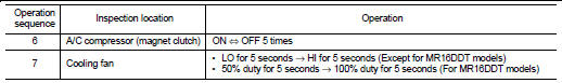
Inspection in Auto Active Test Mode When auto active test mode is actuated, the following operation sequence is repeated 3 times.
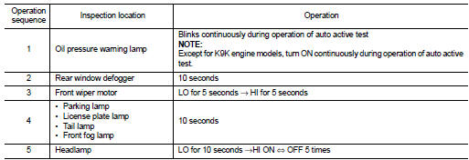
Concept of auto active test
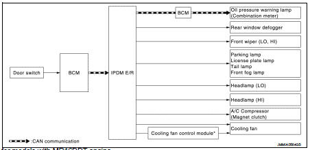
*: Only for models with MR16DDT engine
• IPDM E/R starts the auto active test with the door switch signals transmitted by BCM via CAN communication.
Therefore, the CAN communication line between IPDM E/R and BCM is considered normal if the auto active test starts successfully.
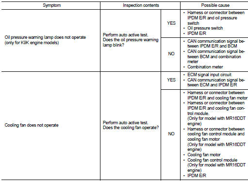
• The auto active test facilitates troubleshooting if any systems controlled by IPDM E/R cannot be operated.
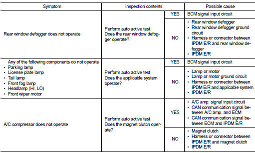
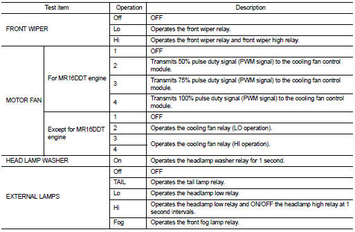
Diagnosis chart in auto active test mode
Consult-III Function (IPDM E/R)
APPLICATION ITEM
CONSULT-III performs the following functions via CAN communication with IPDM E/R.
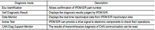
SELF DIAGNOSTIC RESULT
Refer to PCS-55, "DTC Index".
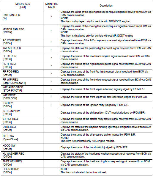
DATA MONITOR
Monitor item
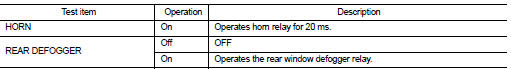
ACTIVE TEST
Test item
 System
Relay control system
RELAY CONTROL SYSTEM : System Diagram
*1: Except for MR16DDT engine models
*2: For MR16DDT engine models
RELAY CONTROL SYSTEM : System Description
IPDM E/R activates the in ...
 ECU diagnosis information
IPDM E/R
Reference Value
VALUES ON THE DIAGNOSIS TOOL
TERMINAL LAYOUT
PHYSICAL VALUES
*1: MR16DDT engine models
*2: Except MR16DDT engine models
*3: CVT models
*4: M/T models
*5 ...
Other materials:
Blower fan on signal
Component Function Check
1.CHECK BLOWER FAN ON SIGNAL
With CONSULT-III
1. Turn ignition switch ON.
2. Select “AIR CONDITIONER” of “BCM” using CONSULT-III.
3. Select “FAN ON SIG” in “DATA MONITOR” mode.
4. Check blower fan ON signal when the fan control dial is operated.
Is t ...
Forward-facing child restraint installation using LATCH
A critical safety limitation applies to the LATCH system: do not utilize the lower anchors if the combined weight of the child and the child restraint exceeds 65 lbs. (29.5 kg). If the total weight surpasses this limit, you must secure the child restraint using the vehicle's standard seat belt syste ...
Rear window and outside mirror defroster switch
Type A
Type B
To defog/defrost the rear window glass and outside mirrors (if so equipped),
start the engine and push the switch 1 on. The indicator light 2 will illuminate.
Push the switch again to turn the defroster off.
It will automatically turn off in approximately 15 minutes.
CAUTIO ...
