Nissan Juke Service and Repair Manual : Front wiper motor lo circuit
Component Function Check
1.CHECK FRONT WIPER LO OPERATION
 CONSULT-III ACTIVE TEST
1. Select “FRONT WIPER” of IPDM E/R active test item.
2. With operating the test item, check front wiper operation.
Lo : Front wiper (LO) operation Off : Stop the front wiper.
Is front wiper (LO) operation normally? YES >> Front wiper motor LO circuit is normal.
NO >> Refer to WW-38, "Diagnosis Procedure".
Diagnosis Procedure
1.CHECK FRONT WIPER MOTOR (LO) OUTPUT VOLTAGE
 CONSULT-III ACTIVE TEST
1. Turn ignition switch OFF.
2. Disconnect front wiper motor connector.
3. Turn ignition switch ON.
4. Select “FRONT WIPER” of IPDM E/R active test item.
5. With operating the test item, check voltage between front wiper motor harness connector and ground.
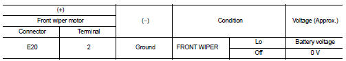
Is the inspection result normal? YES >> Replace front wiper motor.
NO >> GO TO 2.
2.CHECK FRONT WIPER MOTOR (LO) CIRCUIT
1. Turn ignition switch OFF.
2. Disconnect IPDM E/R connector.
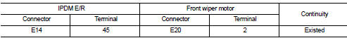
3. Check continuity between IPDM E/R harness connector and front wiper motor harness connector.
4. Check continuity between IPDM E/R harness connector and ground.
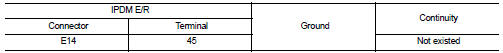
Is the inspection result normal? YES >> Replace IPDM E/R.
NO >> Repair or replace harness.

 Front wiper motor hi circuit
Component Function Check
1.CHECK FRONT WIPER HI OPERATION
CONSULT-III ACTIVE TEST
1. Select “FRONT WIPER” of IPDM E/R active test item.
2. With operating the test item, check front wiper opera ...
Other materials:
Calibration of decel G sensor
Description
TCM stores calibration data (inherent characteristic value) of G sensor to
provide accurate control. Therefore,
it is required to perform calibration of G sensor after the following work is
performed.
• Removal/installation or replacement of G sensor
• Replacement of TCM
P ...
P1651 starter motor relay
Description
ECM controls ON/OFF state of the starter relay, according to the engine and
vehicle condition. Models with no
Intelligent Key System transmit a control signal directly to IPDM E/R. On the
other hand, models with the Intelligent
Key System transmit a control signal to IPDM E/R by w ...
P0524 engine oil pressure
DTC Logic
DTC DETECTION LOGIC
NOTE:
If DTC P0524 is displayed with DTC P0520 or P0075, perform trouble diagnosis for
DTC P0520 or P0075
first. Refer to EC-674, "DTC Logic" or EC-583, "DTC Logic".
DTC CONFIRMATION PROCEDURE
1.PRECONDITIONING
If DTC Confirmation Procedur ...
