Nissan Juke Service and Repair Manual : Wiring diagram
IPDM E/R
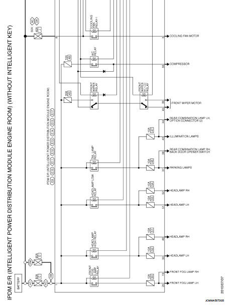
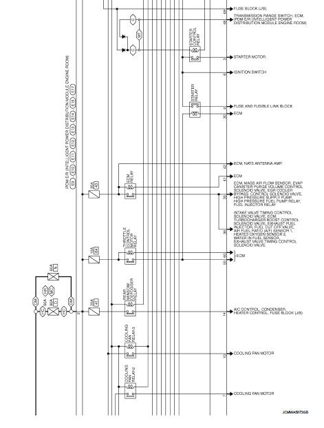
Wiring Diagram
For connector terminal arrangements, harness layouts, and alphabets in a
 (option abbreviation; if not
described in wiring diagram), refer to GI-12, "Connector Information/Explanation
of Option Abbreviation".

 ECU diagnosis information
IPDM E/R
Reference Value
VALUES ON THE DIAGNOSIS TOOL
TERMINAL LAYOUT
PHYSICAL VALUES
*1: MR16DDT engine models
*2: Except MR16DDT engine models
*3: CVT models
*4: M/T models
*5 ...

Other materials:
Engine maintenance (K9K)
Drive belt
DRIVE BELT : Checking Drive Belts
WARNING:
Be sure to perform when the engine is stopped.
1. Inspect belts for cracks, fraying, wear and oil. If necessary,
replace.
2. Evaluate manually if the belt is enough tensioned (tension cannot
be measured by way of frequency meter).
CAU ...
B1082 seat belt Pre-tensioner RH
DTC Logic
DTC DETECTION LOGIC
DTC CONFIRMATION PROCEDURE
1.CHECK SELF-DIAG RESULT
With CONSULT-III
1. Turn ignition switch ON.
2. Perform “Self Diagnostic Result” mode of “AIR BAG” using CONSULT-III.
Without CONSULT-III
1. Turn ignition switch ON.
2. Check the air bag warning la ...
NISSAN Intelligent Key
NISSAN Intelligent Key fob (supplied as two complete sets)
Emergency mechanical key (integrated inside the fob)
Key number plate (one unique metal stamp plate)
Your vehicle is protected by advanced security pairing, meaning it can only be ...
