Nissan Juke Service and Repair Manual : ECU diagnosis information
IPDM E/R
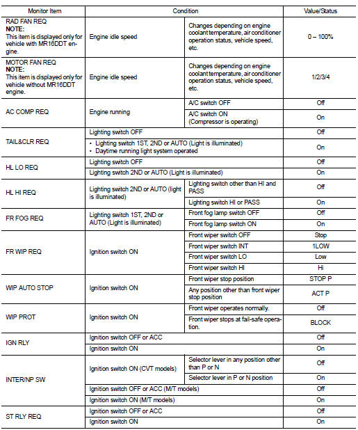
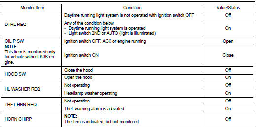
Reference Value
VALUES ON THE DIAGNOSIS TOOL
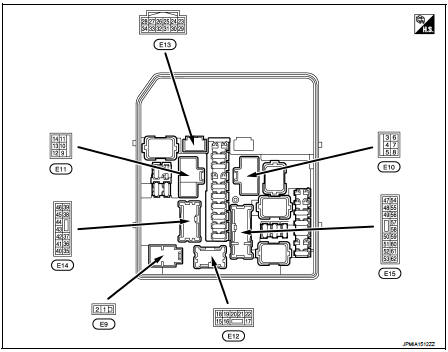
TERMINAL LAYOUT
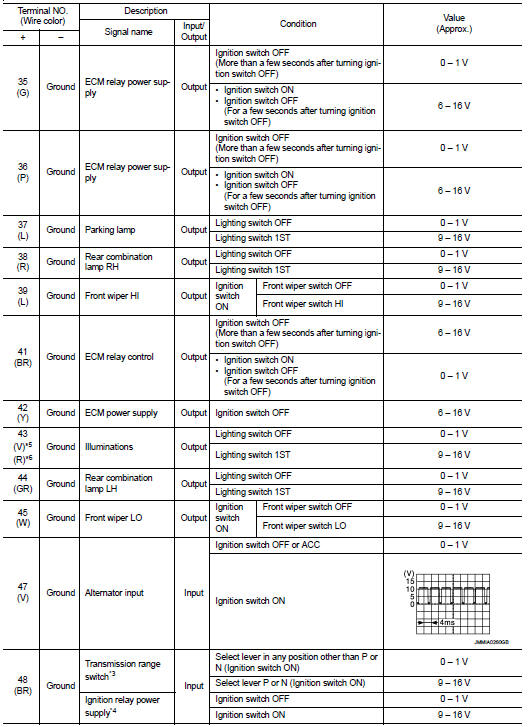
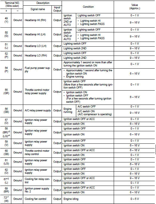
PHYSICAL VALUES
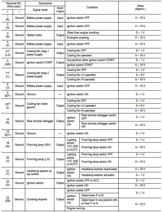

*1: MR16DDT engine models
*2: Except MR16DDT engine models
*3: CVT models
*4: M/T models
*5: With daytime running light system
*6: Without daytime running light system
*7: K9K engine models
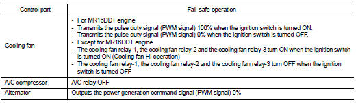
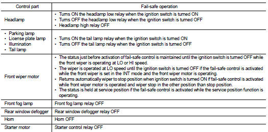
Fail-Safe
CAN COMMUNICATION CONTROL
When CAN communication with ECM and BCM is impossible, IPDM E/R performs fail-safe control. After CAN communication recovers normally, it also returns to normal control.
If No CAN Communication Is Available With ECM
If No CAN Communication Is Available With BCM
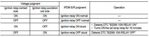
IGNITION RELAY MALFUNCTION DETECTION FUNCTION
ŌĆó IPDM E/R monitors the voltage at the contact circuit and excitation coil circuit of the ignition relay inside it.
ŌĆó IPDM E/R judges the ignition relay error if the voltage differs between the contact circuit and the excitation coil circuit.
ŌĆó If the ignition relay cannot turn OFF due to contact seizure, it activates the tail lamp relay for 10 minutes to alert the user to the ignition relay malfunction when the ignition switch is turned OFF.
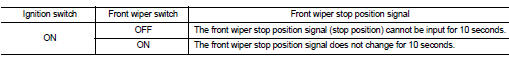
FRONT WIPER PROTECTION FUNCTION
IPDM E/R detects front wiper stop position by a front wiper stop position signal.
When a front wiper stop position signal is in the conditions listed below, IPDM E/R stops power supply to wiper after repeating a front wiper 10 seconds activation and 20 seconds stop.
NOTE
:
This operation status can be confirmed on the IPDM E/R ŌĆ£Data MonitorŌĆØ that
displays ŌĆ£BLOCKŌĆØ for the item
ŌĆ£WIP PROTŌĆØ while the wiper is stopped.
STARTER MOTOR PROTECTION FUNCTION
IPDM E/R turns OFF the starter control relay to protect the starter motor when the starter control relay remains active for 90 seconds.
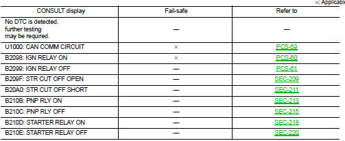
DTC Index
NOTE
:
ŌĆó The details of time display are as follows.
- CRNT: A malfunction is detected now.
- PAST: A malfunction was detected in the past.
ŌĆó IGN counter is displayed on FFD (Freeze Frame Data).
- The number is 0 when is detected now.
- The number increases like 1 → 2 ┬Ę┬Ę┬Ę 38 → 39 after returning to the normal condition whenever IGN OFF → ON.
- The number is fixed to 39 until the self-diagnosis results are erased if it is over 39.
 Diagnosis system (IPDM E/R)
Diagnosis Description
AUTO ACTIVE TEST
Description
In auto active test mode, the IPDM E/R sends a drive signal to the following
systems to check their operation.
ŌĆó Oil pressure warning lamp ...
 Wiring diagram
IPDM E/R
Wiring Diagram
For connector terminal arrangements, harness layouts, and alphabets in a
(option abbreviation; if not
described in wiring diagram), refer to GI-12, "Connector Informat ...
Other materials:
Spiral cable
Exploded View
1. Steering column upper cover
2. Steering column assembly
3. Steering column lower cover
4. Side lid LH
5. TORX bolt
6. Driver air bag module
7. TORX bolt
8. Side lid RH
9. Steering wheel
10. Spiral cable
11. Steering angle sensor
12. Combination switch
13. Stee ...
Engine stand setting
NOTE:
Explained here is how to disassemble with engine stand supporting transaxle
surface. When using different
type of engine stand, note with difference in steps and etc.
1. Remove the engine and the transaxle assembly from the vehicle, and separate
the transaxle from the
engine. Refer t ...
Battery terminal with fusible link
Exploded View
1 : Battery terminal with fusible link
2 : Harness connector
: N┬Ęm (kg-m, ft-lb)
Removal and Installation
REMOVAL
1. Disconnect the battery cable from the negative terminal.
2. Remove cover of battery positive terminal.
3. Remove harness mounting nut and battery terminal wit ...
