Nissan Juke Service and Repair Manual : U1000 can comm
Description
CAN (Controller Area Network) is a serial communication line for real time applications. It is an on-vehicle multiplex communication line with high data communication speed and excellent error detection ability. Modern vehicle is equipped with many electronic control unit, and each control unit shares information and links with other control units during operation (not independent). In CAN communication, control units are connected with 2 communication lines (CAN-H line, CAN-L line) allowing a high rate of information transmission with less wiring. Each control unit transmits/receives data but selectively reads required data only.
CAN Communication Signal Chart. Refer to LAN-31, "CAN COMMUNICATION SYSTEM : CAN Communication Signal Chart".
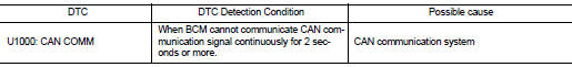
DTC Logic
DTC DETECTION LOGIC
Diagnosis Procedure
1.PERFORM SELF DIAGNOSTIC
1. Turn ignition switch ON and wait for 2 seconds or more.
2. Check “Self Diagnostic Result” of BCM.
Is “CAN COMM CIRCUIT” displayed? YES >> Refer to LAN-17, "Trouble Diagnosis Flow Chart".
NO >> Refer to GI-42, "Intermittent Incident".

 U1010 control unit (can)
DTC Logic
DTC DETECTION LOGIC
Diagnosis Procedure
1.REPLACE BCM
When DTC “U1010” is detected, replace BCM.
>> Replace BCM. Refer to BCS-161, "Removal and Installation". ...
Other materials:
Cup holders
Front
CAUTION
Avoid abrupt starting, sharp cornering, and sudden braking when the central cup holder is being used to prevent spilling your beverages. If the container holds hot liquid, accidental spills can severely scald you or your passenger.
...
P0011 IVT control
DTC Logic
DTC DETECTION LOGIC
NOTE:
If DTC P0011 is displayed with DTC P0075, first perform the trouble diagnosis
for EC-307, "DTC Logic".
DTC CONFIRMATION PROCEDURE
1.PRECONDITIONING
If DTC Confirmation Procedure has been previously conducted, always perform
the following proc ...
Heated seat switch
Exploded View
1. Heated seat swich
2. Switch bracket
3. Console switch finisher
Removal and Installation
REMOVAL
CAUTION:
When removing and installing, use shop cloths to protect from damage.
1. Remove the console switch finisher. Refer to IP-23, "Removal and
Installation".
...
