Nissan Juke Service and Repair Manual : P0132 A/F sensor 1
DTC Logic
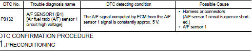
DTC DETECTION LOGIC
To judge the malfunction, the diagnosis checks that the A/F signal computed by ECM from the A/F sensor 1 signal is not inordinately high.
DTC CONFIRMATION PROCEDURE
1.PRECONDITIONING
If DTC Confirmation Procedure has been previously conducted, always perform the following procedure before conducting the next test.
1. Turn ignition switch OFF and wait at least 10 seconds.
2. Turn ignition switch ON.
3. Turn ignition switch OFF and wait at least 10 seconds.
TESTING CONDITION:
Before performing the following procedure, confirm that battery voltage is more
than 10.5 V at idle.
>> GO TO 2.
2.CHECK A/F SENSOR FUNCTION
 With CONSULT-III
1. Start engine and warm it up to normal operating temperature.
2. Select “A/F SEN1 (B1)” in “DATA MONITOR” mode of “ENGINE” using CONSULT-III.
3. Check “A/F SEN1 (B1)” indication.
 With GST
Follow the procedure “With CONSULT-III” above.
Is the indication constantly approx. 5 V? YES >> Proceed to EC-213, "Diagnosis Procedure".
NO >> GO TO 3.
3.PERFORM DTC CONFIRMATION PROCEDURE
With CONSULT-III
1. Turn ignition switch OFF, wait at least 10 seconds and then restart engine.
2. Drive and accelerate vehicle to more than 40 km/h (25 MPH) within 20 seconds after restarting engine.
CAUTION:
Always drive vehicle at a safe speed.
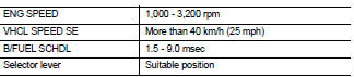
3. Maintain the following conditions for about 20 consecutive seconds.
NOTE:
• Keep the accelerator pedal as steady as possible during the cruising.
• If this procedure is not completed within 1 minute after restarting engine at step 1, return to step 1.
4. Check 1st trip DTC.
 With GST
Follow the procedure “With CONSULT-III” above.
Is 1st trip DTC is detected? YES >> Proceed to EC-213, "Diagnosis Procedure".
NO >> INSPECTION END
Component Inspection
1.CHECK AIR FUEL RATIO (A/F) SENSOR 1 POWER SUPPLY
1. Turn ignition switch OFF.
2. Disconnect A/F sensor 1 harness connector.
3. Turn ignition switch ON.
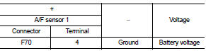
4. Check the voltage between A/F sensor 1 harness connector and ground.
Is the inspection result normal? YES >> GO TO 3.
NO >> GO TO 2.
2.CHECK AIR FUEL RATIO (A/F) SENSOR 1 POWER SUPPLY CIRCUIT
1. Turn ignition switch OFF.
2. Disconnect IPDM E/R harness connector.
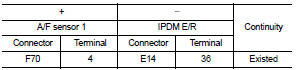
3. Check the continuity between A/F sensor 1 harness connector and IPDM E/R harness connector.
4. Also check harness for short to ground.
Is the inspection result normal? YES >> Perform the trouble diagnosis for power supply circuit.
NO >> Repair or replace error-detected parts.
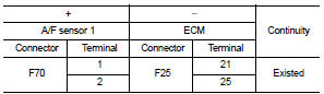
3.CHECK A/F SENSOR 1 INPUT SIGNAL CIRCUIT
1. Turn ignition switch OFF.
2. Disconnect ECM harness connector.
3. Check the continuity between A/F sensor 1 harness connector and ECM harness connector.
4. Check the continuity between A/F sensor 1 harness connector and ground, or ECM harness connector and ground.
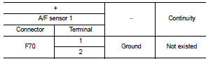
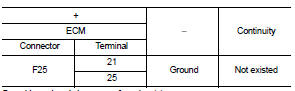
5. Also check harness for short to power.
Is the inspection result normal? YES >> GO TO 4.
NO >> Repair or replace error-detected parts.
4.CHECK INTERMITTENT INCIDENT
Perform GI-42, "Intermittent Incident".
Is the inspection result normal? YES >> GO TO 5.
NO >> Repair or replace error-detected parts.
5.REPLACE AIR FUEL RATIO (A/F) SENSOR 1
Replace air fuel ratio (A/F) sensor 1. Refer to EM-38, "Exploded View".
CAUTION:
• Discard any sensor which has been dropped from a height of more than 0.5 m
(19.7 in) onto a hard
surface such as a concrete floor; use a new one.
• Before installing new sensor, clean exhaust system threads using Oxygen Sensor Thread Cleaner [commercial service tool (J-43897-18 or J43897-12)] and approved Anti-seize Lubricant (commercial service tool).
>> INSPECTION END
 P0131 A/F sensor 1
DTC Logic
DTC DETECTION LOGIC
To judge the malfunction, the diagnosis checks that the A/F signal computed
by ECM from the A/F sensor 1
signal is not inordinately low.
DTC CONFIRMATION PROCEDUR ...
 P0133 A/F sensor 1
DTC Logic
DTC DETECTION LOGIC
To judge the malfunction of A/F sensor 1, this diagnosis measures response
time of the A/F signal computed
by ECM from the A/F sensor 1 signal. The time is compensat ...
Other materials:
Ecu diagnosis information
AUDIO UNIT
Reference Value
TERMINAL LAYOUT
PHYSICAL VALUES
• *1: Models with USB connection function
• *2: Models without USB connection function ...
Vehicle security system
The vehicle security system acts as a primary deterrent by triggering powerful visual and audible alarm signals if unauthorized access is attempted through any of the doors or the rear hatch while the system is armed. Please note that this is a perimeter-based protection system; it is not a motion-d ...
Drive belt
1. Alternator
2. Drive belt auto-tensioner
3. Crankshaft pulley
4. Air conditioner compressor
5. Water pump
WARNING
Be sure the ignition switch is in the OFF or LOCK position before servicing
drive belts. The engine could rotate unexpectedly.
1. Visually inspect the belt for signs of unus ...
