Nissan Juke Service and Repair Manual : P0131 A/F sensor 1
DTC Logic
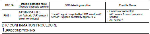
DTC DETECTION LOGIC
To judge the malfunction, the diagnosis checks that the A/F signal computed by ECM from the A/F sensor 1 signal is not inordinately low.
DTC CONFIRMATION PROCEDURE
1.PRECONDITIONING
If DTC Confirmation Procedure has been previously conducted, always perform the following procedure before conducting the next test.
1. Turn ignition switch OFF and wait at least 10 seconds.
2. Turn ignition switch ON.
3. Turn ignition switch OFF and wait at least 10 seconds.
TESTING CONDITION:
Before performing the following procedure, confirm that battery voltage is more
than 10.5 V at idle.
>> GO TO 2.
2.CHECK A/F SENSOR FUNCTION
 With CONSULT-III
1. Start engine and warm it up to normal operating temperature.
2. Select ŌĆ£A/F SEN1 (B1)ŌĆØ in ŌĆ£DATA MONITORŌĆØ mode of ŌĆ£ENGINEŌĆØ using CONSULT-III.
3. Check ŌĆ£A/F SEN1 (B1)ŌĆØ indication.
 With GST
Follow the procedure ŌĆ£With CONSULT-IIIŌĆØ above.
Is the indication constantly approx. 0 V? YES >> Proceed to EC-210, "Diagnosis Procedure".
NO >> GO TO 3.
3.PERFORM DTC CONFIRMATION PROCEDURE
With CONSULT-III
1. Turn ignition switch OFF, wait at least 10 seconds and then restart engine.
2. Drive and accelerate vehicle to more than 40 km/h (25 MPH) within 20 seconds after restarting engine.
CAUTION:
Always drive vehicle at a safe speed
.
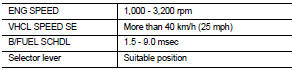
3. Maintain the following conditions for about 20 consecutive seconds.
NOTE:
ŌĆó Keep the accelerator pedal as steady as possible during the cruising.
ŌĆó If this procedure is not completed within 1 minute after restarting engine at step 1, return to step 1.
4. Check 1st trip DTC.
 With GST
Follow the procedure ŌĆ£With CONSULT-IIIŌĆØ above.
Is 1st trip DTC detected? YES >> Proceed to EC-210, "Diagnosis Procedure".
NO >> INSPECTION END
Component Inspection
1.CHECK AIR FUEL RATIO (A/F) SENSOR 1 POWER SUPPLY
1. Turn ignition switch OFF.
2. Disconnect A/F sensor 1 harness connector.
3. Turn ignition switch ON.
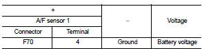
4. Check the voltage between A/F sensor 1 harness connector and ground.
Is the inspection result normal? YES >> GO TO 3.
NO >> GO TO 2.
2.CHECK AIR FUEL RATIO (A/F) SENSOR 1 POWER SUPPLY CIRCUIT
1. Turn ignition switch OFF.
2. Disconnect IPDM E/R harness connector.
3. Check the continuity between A/F sensor 1 harness connector and IPDM E/R harness connector.

4. Also check harness for short to ground.
Is the inspection result normal? YES >> Perform the trouble diagnosis for power supply circuit.
NO >> Repair or replace error-detected parts.
3.CHECK A/F SENSOR 1 INPUT SIGNAL CIRCUIT
1. Turn ignition switch OFF.
2. Disconnect ECM harness connector.
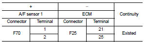
3. Check the continuity between A/F sensor 1 harness connector and ECM harness connector.
4. Check the continuity between A/F sensor 1 harness connector and ground, or ECM harness connector and ground.
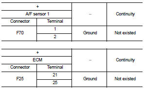
5. Also check harness for short to power.
Is the inspection result normal? YES >> GO TO 4.
NO >> Repair or replace error-detected parts.
4.CHECK INTERMITTENT INCIDENT
Perform GI-42, "Intermittent Incident".
Is the inspection result normal? YES >> GO TO 5.
NO >> Repair or replace error-detected parts.
5.REPLACE AIR FUEL RATIO (A/F) SENSOR 1
Replace air fuel ratio (A/F) sensor 1. Refer to EM-38, "Exploded View".
CAUTION:
ŌĆó Discard any sensor which has been dropped from a height of more than 0.5 m
(19.7 in) onto a hard
surface such as a concrete floor; use a new one.
ŌĆó Before installing new sensor, clean exhaust system threads using Oxygen Sensor Thread Cleaner [commercial service tool (J-43897-18 or J43897-12)] and approved Anti-seize Lubricant (commercial service tool).
>> INSPECTION END
 P0130 A/F sensor 1
DTC Logic
DTC DETECTION LOGIC
To judge the malfunction, the diagnosis checks that the A/F signal computed
by ECM from the A/F sensor 1
signal fluctuates according to fuel feedback control.
DTC ...
 P0132 A/F sensor 1
DTC Logic
DTC DETECTION LOGIC
To judge the malfunction, the diagnosis checks that the A/F signal computed
by ECM from the A/F sensor 1
signal is not inordinately high.
DTC CONFIRMATION PROCEDU ...
Other materials:
Rear window defogger switch
With auto A/C
WITH AUTO A/C : Description
ŌĆó The rear window defogger is operated by turning the rear window defogger
switch ON.
ŌĆó The indicator lamp in the rear window defogger switch illuminates when the
rear window defogger is operating.
WITH AUTO A/C : Component Function Check
1.CHEC ...
B2604 shift position
DTC Logic
DTC DETECTION LOGIC
NOTE:
ŌĆó If DTC B2604 is displayed with DTC U1000, first perform the trouble diagnosis
for DTC U1000. Refer to
BCS-83, "DTC Logic".
ŌĆó If DTC B2604 is displayed with DTC U1010, first perform the trouble diagnosis
for DTC U1010. Refer to
BCS-84, &qu ...
Service Equipment
RECOVERY/RECYCLING RECHARGING EQUIPMENT
Be certain to follow the manufacturerŌĆÖs instructions for machine operation
and machine maintenance. Never
introduce any refrigerant other than that specified into the machine.
ELECTRICAL LEAK DETECTOR
Be certain to follow the manufacturerŌĆÖs instruc ...
