Nissan Juke Service and Repair Manual : Service Equipment
RECOVERY/RECYCLING RECHARGING EQUIPMENT
Be certain to follow the manufacturerŌĆÖs instructions for machine operation and machine maintenance. Never introduce any refrigerant other than that specified into the machine.
ELECTRICAL LEAK DETECTOR
Be certain to follow the manufacturerŌĆÖs instructions for tester operation and tester maintenance.
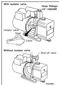
VACUUM PUMP
The lubricant contained inside the vacuum pump is not compatible with the specified lubricant for HFC-134a (R-134a) A/C systems.
The vent side of the vacuum pump is exposed to atmospheric pressure.
So the vacuum pump lubricant may migrate out of the pump into the service hose. This is possible when the pump is switched OFF after evacuation (vacuuming) and hose is connected to it.
To prevent this migration, use a manual valve placed near the hoseto- pump connection, as per the following.
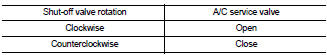
ŌĆó Vacuum pumps usually have a manual isolator valve as part of the pump. Close this valve to isolate the service hose from the pump.
ŌĆó Use a hose equipped with a manual shut-off valve near the pump end for pumps without an isolator. Close the valve to isolate the hose from the pump.
ŌĆó Disconnect the hose from the pump if the hose has an automatic shut-off valve. As long as the hose is connected, the valve is open and lubricating oil may migrate.
Some one-way valves open when vacuum is applied and close under no vacuum condition. Such valves may restrict the pumpŌĆÖs ability to pull a deep vacuum and are not recommended.
MANIFOLD GAUGE SET
Be certain that the gauge face indicates HFC-134a or R-134a. Be sure the gauge set has 1/2″-16 ACME threaded connections for service hoses. Confirm the set has been used only with refrigerant HFC-134a (R-134a) and specified lubricants.
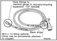
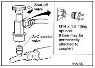
SERVICE HOSES
Be certain that the service hoses display the markings described (colored hose with black stripe). All hoses must equip positive shutoff devices (either manual or automatic) near the end of the hoses opposite to the manifold gauge.
SERVICE COUPLERS
Never attempt to connect HFC-134a (R-134a) service couplers to the CFC-12 (R-12) A/C system. The HFC-134a (R-134a) couplers do not properly connect to the CFC-12 (R-12) system. However, if an improper connection is attempted, discharging and contamination may occur.
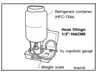
REFRIGERANT WEIGHT SCALE
Verify that no refrigerant other than HFC-134a (R-134a) and specified lubricants have been used with the scale. The hose fitting must be 1/2″-16 ACME if the scale controls refrigerant flow electronically.
CALIBRATING ACR4 WEIGHT SCALE
Calibrate the scale each three month.
To calibrate the weight scale on the ACR4:
1. Press ŌĆ£Shift/ResetŌĆØ and ŌĆ£EnterŌĆØ at the same time.
2. Press ŌĆ£8787ŌĆØ. ŌĆ£A1ŌĆØ is displayed.
3. Remove all weight from the scale.
4. Press ŌĆ£0ŌĆØ, then press ŌĆ£EnterŌĆØ. ŌĆ£0.00ŌĆØ is displayed and change to ŌĆ£A2ŌĆØ.
5. Place a known weight (dumbbell or similar weight), between 4.5 and 8.6 kg (10 and 19 lb.) on the center of the weight scale.
6. Enter the known weight using four digits. (Example 10 lb. = 10.00, 10.5 lb. =
10.50)
7. Press ŌĆ£EnterŌĆØŌĆö the display returns to the vacuum mode.
8. Press ŌĆ£Shift/ResetŌĆØ and ŌĆ£EnterŌĆØ at the same time.
9. Press ŌĆ£6ŌĆØŌĆö the known weight on the scale is displayed.
10. Remove the known weight from the scale. ŌĆ£0.00ŌĆØ is displayed.
11. Press ŌĆ£Shift/ResetŌĆØ to return the ACR4 to the program mode.
CHARGING CYLINDER
Using a charging cylinder is not recommended. Refrigerant may be vented into air from cylinderŌĆÖs top valve when filling the cylinder with refrigerant. Also, the accuracy of the cylinder is generally less than that of an electronic scale or of quality recycle/recharge equipment.
 Precautions For Refrigerant System Service
GENERAL REFRIGERANT PRECAUTION
WARNING:
ŌĆó Never breathe A/C refrigerant and lubricant vapor or mist. Exposure may
irritate eyes, nose and
throat. Use only approved recovery/recycling equipment ...
 Preparation
...
Other materials:
P0100 MAF sensor
DTC Logic
DTC DETECTION LOGIC
Diagnosis Procedure
1.CHECK GROUND CONNECTIONS
1. Turn ignition switch OFF.
2. Check ground connection E38. Refer to Ground inspection in GI-44, "Circuit
Inspection".
Is the inspection result normal?
YES >> GO TO 2.
NO >> Repair or ...
P0110 IAT sensor
DTC Logic
DTC DETECTION LOGIC
Diagnosis Procedure
1.CHECK GROUND CONNECTIONS
1. Turn ignition switch OFF.
2. Check ground connection E38. Refer to Ground inspection in GI-44, "Circuit
Inspection".
Is the inspection result normal?
YES >> GO TO 2.
NO >> Repair or ...
Precaution for Brake Control system
ŌĆó Always perform a pre-driving check to drive the vehicle.
ŌĆó Always check speed and safety while driving the vehicle.
ŌĆó To operate CONSULT-III while driving, more than one person is required to be
in the vehicle to avoid interference
to driving and ensure safety.
ŌĆó Slight vibrations ar ...
