Nissan Juke Service and Repair Manual : Wiring diagram
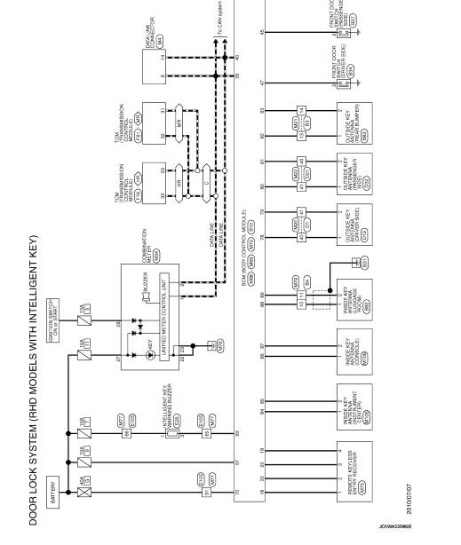
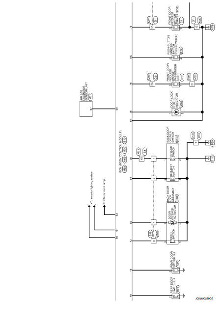
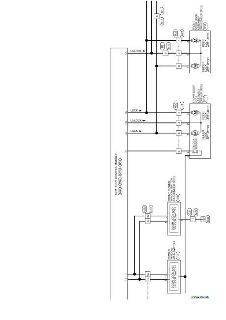
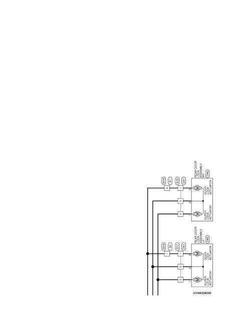
DOOR & LOCK SYSTEM
Wiring Diagram
For connector terminal arrangements, harness layouts, and alphabets in a
 (option abbreviation; if not
described in wiring diagram), refer to GI-12, "Connector Information/Explanation
of Option Abbreviation".
 ECU diagnosis information
BCM
List of ECU Reference
...
 Basic inspection
DIAGNOSIS AND REPAIR WORK FLOW
Work Flow
OVERALL SEQUENCE
DETAILED FLOW
1.GET INFORMATION FOR SYMPTOM
1. Get detailed information from the customer about the symptom (the
condition and the en ...
Other materials:
Meters and gauges
1. Tachometer
2. Engine coolant temperature gauge
3. Vehicle information display
— Odometer/twin trip odometer
— Trip computer
— Torque vectoring AWD (AWD model)
— Outside air temperature
4. Fuel gauge
5. Speedometer
6. Warning/indicator lights
7. Instrument brightness ...
Unit removal and installation
TRANSMISSION ASSEMBLY
Exploded View
1. Transaxle assembly
A: : For the tightening torque, refer to TM-508, "Removal and Installation".
Removal and Installation
REMOVAL
WARNING:
Never open the radiator cap or drain plug when the engine is hot. Hot liquid may
spray out, causing
s ...
Engine overheating
Description
CHART 17: ENGINE OVERHEATING
Diagnosis Procedure
1.CHECK COOLING SYSTEM
Check the cooling system. Refer to CO-60, "Troubleshooting Chart".
Is the inspection result normal?
YES >> GO TO 2.
NO >> Repair or replace.
2.CHECK ECM POWER SUPPLY AND GROUND CIR ...
