Nissan Juke Service and Repair Manual : B2604 shift position
DTC Logic
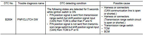
DTC DETECTION LOGIC
NOTE
:
• If DTC B2604 is displayed with DTC U1000, first perform the trouble diagnosis
for DTC U1000. Refer to
BCS-83, "DTC Logic".
• If DTC B2604 is displayed with DTC U1010, first perform the trouble diagnosis for DTC U1010. Refer to BCS-84, "DTC Logic".
DTC CONFIRMATION PROCEDURE
1.PERFORM DTC CONFIRMATION PROCEDURE
1. Shift the selector lever to the P position.
2. Turn ignition switch ON and wait 5 seconds or more.
3. Shift the selector lever to the N position and wait 5 seconds or more.
4. Shift the selector lever to any position other than P and N, and wait 5 seconds or more.
5. Check DTC in “Self Diagnostic Result” mode of “BCM” using CONSULT-III.
Is DTC detected? YES >> Go to SEC-88, "Diagnosis Procedure".
NO >> INSPECTION END
Diagnosis Procedure
1.CHECK DTC OF TCM
Check DTC in “Self Diagnostic Result” mode of “TCM” using CONSULT-III.
Is DTC detected? YES >> Perform the trouble diagnosis related to the detected DTC. Refer to TM-171, "DTC Index" (CVT: RE0F10B) or TM-366, "DTC Index" (CVT: RE0F11A).
NO >> GO TO 2.
2.CHECK BCM INPUT SIGNAL
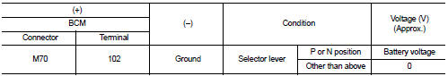
1. Turn ignition switch ON.
2. Check voltage between BCM harness connector and ground.
Is the inspection result normal? YES >> GO TO 3.
NO >> GO TO 4.
3.REPLACE BCM
1. Replace BCM. Refer to BCS-93, "Removal and Installation".
2. Perform initialization of BCM and registration of all Intelligent Keys using CONSULT-III.
For initialization and registration procedures, refer to CONSULT-III Operation Manual NATS-IVIS/NVIS.
>> INSPECTION END
4.CHECK BCM INPUT SIGNAL CIRCUIT
1. Turn ignition switch OFF.
2. Disconnect transmission range switch connector.
3. Disconnect BCM connector.
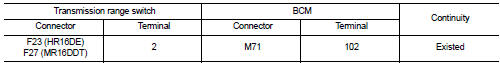
4. Check continuity between transmission range switch harness connector and BCM harness connector.
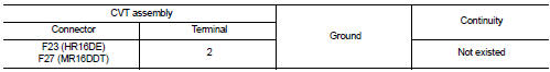
5. Check continuity between CVT assembly harness connector and ground.
Is the inspection result normal? YES >> GO TO 5.
NO >> Repair or replace harness.
5.CHECK INTERMITTENT INCIDENT
Refer to GI-42, "Intermittent Incident".
>> INSPECTION END
 B2603 shift position
DTC Logic
DTC DETECTION LOGIC
NOTE:
• If DTC B2603 is displayed with DTC B2601, first perform the trouble diagnosis
for DTC B2601. Refer to
SEC-79, "DTC Logic".
DTC CONFIRMATION P ...
 B2605 shift position
DTC Logic
DTC DETECTION LOGIC
NOTE:
• If DTC B2605 is displayed with DTC U1000, first perform the trouble diagnosis
for DTC U1000. Refer to
BCS-83, "DTC Logic".
• If DTC B2605 is ...
Other materials:
P1226 TP sensor
DTC Logic
DTC DETECTION LOGIC
DTC CONFIRMATION PROCEDURE
1.PRECONDITIONING
If DTC Confirmation Procedure has been previously conducted, always turn
ignition switch OFF and wait at
least 10 seconds before conducting the next test.
TESTING CONDITION:
Before performing the following proced ...
CVT position
Inspection and Adjustment
INSPECTION
1. Turn ON the ignition switch with the selector lever at the P position.
2. Press the selector button with the brake pedal depressed, and confirm that
the lever can be shifted to
positions other than P. Also confirm that shifting is not allowed from the P ...
Engine control system symptoms
Symptom Table
SYSTEM — BASIC ENGINE CONTROL SYSTEM
1 - 6: The numbers refer to the order of inspection.
(continued on next table)
SYSTEM — ENGINE MECHANICAL & OTHER
1 - 6: The numbers refer to the order of inspection ...
