Nissan Juke Service and Repair Manual : Plug
Description
Replace the O-ring if oil leakage or exudes from the plug.
Exploded View
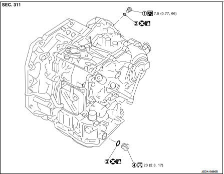
1. Plug
2. O-ring
3. O-ring
4. Plug
 : Always replace after every
disassembly.
 : N·m (kg-m, ft-lb)
 : N·m (kg-m, in-lb)
 : Genuine NISSAN CVT Fluid NS-2
Removal and Insta
NOTE
:
Replace the O-rings if oil leakage or exudes from the plugs.
REMOVAL
Remove the plugs and O-rings.
INSTALLATION
Note the following, and install in the reverse order of removal.
CAUTION:
• Never reuse O-ring.
• Apply Genuine NISSAN CVT Fluid NS-2 to O-ring.
Inspection and Adjustment
INSPECTION AFTER INSTALLATION
Check for CVT fluid leakage. Refer to TM-480, "Inspection".
ADJUSTMENT AFTER INSTALLATION
Adjust the CVT fluid level. Refer to TM-379, "Adjustment".
 Fluid cooler system
Exploded View
1. Bracket
2. Bracket
3. Bracket
4. CVT fluid cooler
5. Clamp
6. CVT fluid cooler hose C
7. CVT fluid cooler hose B
8. CVT fluid cooler tube assembly
9. CVT fluid cooler ...
 Unit removal and installation
TRANSMISSION ASSEMBLY
Exploded View
1. Transaxle assembly
A: : For the tightening torque, refer to TM-508, "Removal and Installation".
Removal and Installation
REMOVAL
WARNING:
Neve ...
Other materials:
Back door
Exploded View
REMOVAL
1. Back door weather-strip
2. Back door stay
3. Back door stay lower bracket
4. Bumper rubber
5. Back door striker
6. Back door panel
7. Back door hinge
8. Hole cover
A : Center mark
B : Seam
: Do not reuse
: Body grease
Back door assembly
BACK DOOR ASSEMB ...
Warning/Indicator lights (yellow)
or
Anti-lock Braking System (ABS) warning light
When you place the power switch in the ON or "READY to drive" position, the Anti-lock Braking System (ABS) warning light will illuminate briefly and then extinguish. This serves as a standard system self-check to confirm ...
Component parts
Component Parts Location
LHD models
1. ABS actuator and electric unit (control
unit)
Refer to BRC-97, "Component Parts
Location".
2. ECM
Refer to EC-25, "ENGINE CONTROL
SYSTEM :
Component Parts Location".
3. Front wheel sensor
Refer to BRC-97, "Component Parts
...
