Nissan Juke Service and Repair Manual : Fluid cooler system
Exploded View
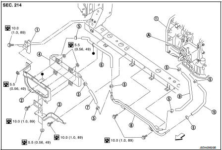
1. Bracket
2. Bracket
3. Bracket
4. CVT fluid cooler
5. Clamp
6. CVT fluid cooler hose C
7. CVT fluid cooler hose B
8. CVT fluid cooler tube assembly
9. CVT fluid cooler hose D
10. CVT fluid cooler hose A
11. Transaxle assembly
A. CVT oil warmer
 : Vehicle front
 : N┬Ęm (kg-m, in-lb)
Removal and Installation
REMOVAL
1. Remove front bumper assembly. Refer to EXT-13, "Removal and Installation".
2. Remove inlet air duct (lower). Refer to EM-161, "Removal and Installation".
3. Remove air guide (LH and RH). Refer to DLK-147, "HR16DE : Exploded View".
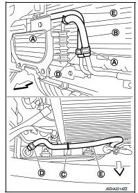
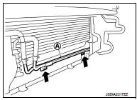
4. Remove hose clamps (A) and fluid cooler hose B (B).
 : Vehicle front
5. Disconnect clip (C) from bracket.
6. Remove hose clamps (D) and fluid cooler hose C (E).
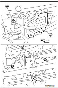
7. Remove nut (A) and bolts (B).
 : Vehicle front
8. Remove CVT fluid cooler (with brackets) (C) from the vehicle.
9. Remove clamps (A) and fluid cooler hose A (B).
 : Vehicle front
NOTE
:
Cap or plug openings to prevent fluid from spilling.
10. Remove clamps (C) and fluid cooler hose A (D).
NOTE
:
Cap or plug openings to prevent fluid from spilling.
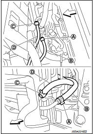
11. Remove CVT fluid cooler tube assembly (A) from the vehicle.
 : Bolt
INSTALLATION
Note the following, and Install in the reverse order of removal.
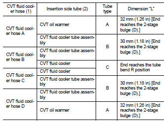
ŌĆó Refer to the following when installing CVT fluid cooler hoses.
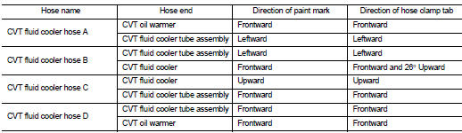
- Insert CVT fluid cooler hose according to dimension ŌĆ£LŌĆØ described below.
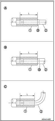
- Set hose clamps (1) at the both ends of CVT fluid cooler hoses (2) with dimension ŌĆ£AŌĆØ from the hose edge.
Tube type A, B Dimension ŌĆ£AŌĆØ : 5 ŌĆō 9 mm (0.20 ŌĆō 0.35 in) Tube type C Dimension ŌĆ£AŌĆØ : 5 mm (0.20 in)
- Hose clamp should not interfere with the bulge of fluid cooler tube.
Inspection and Adjustment
INSPECTION AFTER INSTALLATION
Check for CVT fluid leakage. Refer to TM-480, "Inspection".
ADJUSTMENT AFTER INSTALLATION
Adjust the CVT fluid level. Refer to TM-379, "Adjustment".
 Water hose
Exploded View
1. Hose clamp
2. Water hose A
3. Water hose B
4. Water hose B
5. Water bypass pipe
6. Hose clamp
7. Heater hose
8. Water hose C
A. Water outlet
B. Heater thermostat
C ...
 Plug
Plug
Description
Replace the O-ring if oil leakage or exudes from the plug.
Exploded View
1. Plug
2. O-ring
3. O-ring
4. Plug
: Always replace after every
disassembly.
: N┬Ęm (kg-m, ft-lb)
: ...
Other materials:
B2623 inside antenna
DTC Logic
DTC DETECTION LOGIC
DTC CONFIRMATION PROCEDURE
1.PERFORM DTC CONFIRMATION PROCEDURE
1. Select ŌĆ£INTELLIGENT KEYŌĆØ of ŌĆ£BCMŌĆØ using CONSULT-III.
2. Select ŌĆ£INSIDE ANT DIAGNOSISŌĆØ in ŌĆ£WORK SUPPORTŌĆØ mode.
3. Perform inside key antenna (ŌĆ£INSIDE ANT DIAGNOSISŌĆØ) on ŌĆ£WORK S ...
Precaution for Supplemental Restraint System (SRS) "AIR BAG" and "SEAT BELT
PRE-TENSIONER"
The Supplemental Restraint System such as ŌĆ£AIR BAGŌĆØ and ŌĆ£SEAT BELT PRE-TENSIONERŌĆØ,
used along
with a front seat belt, helps to reduce the risk or severity of injury to the
driver and front passenger for certain
types of collision. Information necessary to service the system safely is
...
Cylinder head
Exploded View
REMOVAL
1. Cylinder head assembly
2. Cylinder head bolt
3. Cylinder head gasket
A. Tightening must be done following
the installation procedure.
Refer to EM-91
: N┬Ęm (kg-m, ft-lb)
: Always replace after every
disassembly.
: Should be lubricated with oil.
DISASSEMBLY ...
