Nissan Juke Service and Repair Manual : Auto retractable door mirror circuit
Component Function Check
1.CHECK FUNCTION
1. Turn the door mirror open/close switch to “AUTO”.
2. Turn ignition switch ON.
3. Select “INTELLIGENT KEY” of “BCM” using CONSULT-III.
4. Select “RETRACTABLE MIRROR” in “ACTIVE TEST” mode.
5. Touch “On” check that it works normally.
Is the inspection result normal? YES >> INSPECTION END
NO >> Refer to MIR-30, "Diagnosis Procedure"
Diagnosis Procedure
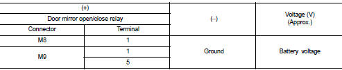
1.CHECK DOOR MIRROR OPEN RELAY AND DOOR MIRROR CLOSE RELAY POWER SUPPLY
1. Turn ignition switch OFF.
2. Disconnect door mirror open relay and door mirror close relay connector.
3. Check voltage between door mirror open relay and door mirror close relay harness connector and ground.
Is the inspection result normal? YES >> GO TO 3.
NO >> GO TO 2.
2.DETECT MALFUNCTIONING PART
Check the following.
• 10 A fuse (#7)
• Harness for open or short between door mirror remote control switch harness
connector and battery terminal.
Is the inspection result normal? YES >> GO TO 8.
NO >> Repair or replace the malfunctioning parts.
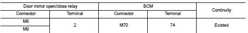
3.CHECK BCM INPUT SIGNAL CIRCUIT
1. Disconnect BCM connector.
2. Check continuity between door mirror open relay and door mirror close relay harness connector and BCM harness connector
3. Check continuity between BCM harness connector and ground.
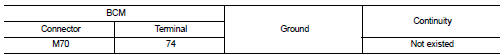
Is the inspection result normal? YES >> GO TO 4.
NO >> Repair or replace harness or connector.
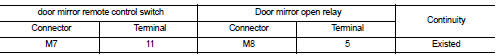
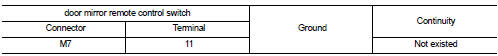
4.CHECK OPEN/CLOSE MOTOR GROUND CIRCUIT
1. Disconnect door mirror remote control switch connector.
2. Check continuity between door mirror remote control switch harness connector and door mirror open relay harness connector.
3. Check continuity between door mirror remote control switch harness connector and ground.
Is the inspection result normal? YES >> GO TO 5.
NO >> Repair or replace harness.
5.CHECK DOOR MIRROR OPEN RELAY
Check door mirror open relay.
Refer to MIR-32, "Component Inspection (Door Mirror Open Relay)" Is the inspection result normal? YES >> GO TO 7.
NO >> Repair or replace harness or connector.
6.CHECK DOOR MIRROR CLOSE RELAY
Check door mirror close relay.
Refer to MIR-32, "Component Inspection (Door Mirror Close Relay)" Is the inspection result normal? YES >> GO TO 7.
NO >> Repair or replace harness or connector.
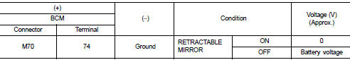
7.CHECK BCM FUNCTION
1. Turn the door mirror open/close switch to AUTO.
2. Connect door mirror remote control switch connector, door mirror open relay, door mirror close relay and BCM connector.
3. Turn ignition switch ON.
4. Select “INTELLIGENT KEY” of “BCM” using CONSULT-III.
5. Select “RETRACTABLE MIRROR” in “ACTIVE TEST” mode.
6. Touch “On” and check voltage between BCM harness connector and ground.
Is the inspection result normal? YES >> GO TO 8.
NO >> Replace BCM. Refer to BCS-93, "Removal and Installation".
8.CHECK INTERMITTENT INCIDENT
Refer to GI-42, "Intermittent Incident"
>> INSPECTION END
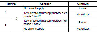
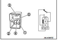
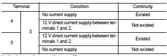
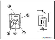
Component Inspection (Door Mirror Open Relay)
1.CHECK DOOR MIRROR OPEN RELAY
1. Turn ignition switch OFF.
2. Remove door mirror open relay.
3. Check the continuity between door mirror open relay terminals under the following conditions.
Is the inspection result normal? YES >> INSPECTION END.
NO >> Replace door mirror open relay.
Component Inspection (Door Mirror Close Relay)
1.CHECK DOOR MIRROR OPEN/CLOSE RELAY
1. Turn ignition switch OFF.
2. Remove door mirror close relay.
3. Check the continuity between door mirror close relay terminals under the following conditions.
Is the inspection result normal? YES >> INSPECTION END.
NO >> Replace door mirror close relay.
 Door mirror (open/close motor)
Component Function Check
1.CHECK DOOR MIRROR RETRACT FUNCTION
1. Turn ignition switch ON.
2. Operate open/close switch. Check that door mirror operates normally.
Is the inspection result normal? ...

Other materials:
Drive belt auto tensioner and idler pulley
Exploded View
1. Front cover
2. Drive belt auto-tensioner
: N·m (kg-m, ft-lb)
Removal and Installation
Removal
1. Loosen mounting bolt and remove drive belt auto-tensioner.
Installation
Install in the reverse order of removal.
CAUTION:
When installing drive belt auto-tensioner, be ...
Precaution
Precautions for Drive Shaft
• Observe the following precautions when disassembling and assembling drive
shaft.
- Never disassemble joint sub-assembly because it is non-overhaul parts.
- Perform work in a location which is as dust-free as possible.
- Clean the parts, before disassembling an ...
P0133 A/F sensor 1
DTC Logic
DTC DETECTION LOGIC
To judge the malfunction of A/F sensor 1, this diagnosis measures response
time of the A/F signal computed
by ECM from the A/F sensor 1 signal. The time is compensated by engine operating
(speed and load), fuel
feedback control constant, and the A/F sensor 1 tem ...
