Nissan Juke Service and Repair Manual : Water hose
Exploded View
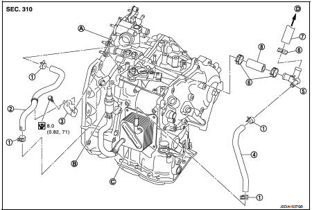
1. Hose clamp
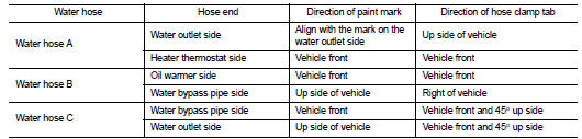
2. Water hose A
3. Water hose B
4. Water hose B
5. Water bypass pipe
6. Hose clamp
7. Heater hose
8. Water hose C
A. Water outlet
B. Heater thermostat
C. Oil warmer
D. Heater core
 : N·m (kg-m, in-lb)
Removal and Installation
REMOVAL
WARNING:
Never remove the radiator cap when the engine is hot. Serious burns could occur
from high pressure
coolant escaping from the radiator.
CAUTION:
Perform these steps after the coolant temperature has cooled sufficiently.
1. Remove the hose clamp and pull out the water hose A.
2. Remove the hose clamp and pull out the water hose B.
3. Remove the hose clamp and pull out the water hose C.
4. Pull out the heater hose and remove the water bypass pipe. Refer to CO-52, "Exploded View".
5. Remove the bracket.
INSTALLATION
Note the following, and install in the reverse order of removal.
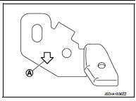
‚ÄĘ To install bracket to the CVT assembly, face the from arrow (A) of the bracket ahead of the vehicle.
‚ÄĘ When installing water hose (1) to tube (2), refer to insertion length ‚ÄúA‚ÄĚ below.
Insertion length ‚ÄúA‚ÄĚ : 27 mm (1.06 in)
‚ÄĘ When hose clamp (1) is installed on CVT water hose (2), refer to dimension ‚ÄúA‚ÄĚ below.
Dimension‚ÄúA‚ÄĚ : 5 ‚Äď 7 mm (0.20 ‚Äď 0.28 in)
‚ÄĘ The hose clamp should not come on bulge (B).
Inspection
INSPECTION AFTER INSTALLATION
Start the engine, and check the joints for coolant leakage.
 Differential side oil seal
Exploded View
1. Transaxle assembly
2. Differential side oil seal (left side)
3. Differential side oil seal (right side)
: Vehicle front
: Always replace after every
disassembly.
: Genuine N ...
 Fluid cooler system
Exploded View
1. Bracket
2. Bracket
3. Bracket
4. CVT fluid cooler
5. Clamp
6. CVT fluid cooler hose C
7. CVT fluid cooler hose B
8. CVT fluid cooler tube assembly
9. CVT fluid cooler ...
Other materials:
P0340 CMP sensor (phase)
DTC Logic
DTC DETECTION LOGIC
Diagnosis Procedure
1.CHECK GROUND CONNECTIONS
1. Turn ignition switch OFF.
2. Check ground connection E38. Refer to Ground inspection in GI-44, "Circuit
Inspection".
Is the inspection result normal?
YES >> GO TO 2.
NO >> Repair or ...
All-Wheel Drive (AWD) mode switch operations
AWD mode switch
The All-Wheel Drive (AWD) system is used to select the 2WD (Two-Wheel Drive),
AWD-V or AWD mode depending on the driving conditions.
The AWD mode indicator lights ( (green),
) are located in the instrument panel.
The AWD mode indicator lights (green)
illuminate when the ig ...
Thermostat
Exploded View
1. Radiator hose (upper)
2. Water inlet
3. Rubber ring
4. Thermostat
A. To radiator
: Always replace after every
disassembly.
: N·m (kg-m, ft-lb)
Removal and Installation
REMOVAL
1. Drain engine coolant from radiator. Refer to CO-37, "Draining".
CAUTION:
...
