Nissan Juke Service and Repair Manual : Security indicator lamp
Component Function Check
1.CHECK FUNCTION
1. Perform ÔÇťTHEFT INDÔÇŁ in the ÔÇťACTIVE TESTÔÇŁ mode of ÔÇťBCMÔÇŁ using CONSULT-III.
2. Check security indicator lamp operation.
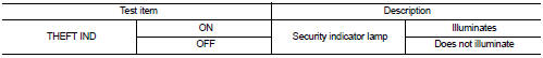
Is the inspection result normal? YES >> INSPECTION END
NO >> Go to SEC-227, "Diagnosis Procedure".
Diagnosis Procedure
1.CHECK SECURITY INDICATOR LAMP POWER SUPPLY CIRCUIT
1. Turn ignition switch OFF.
2. Disconnect combination meter connector.
3. Check voltage between combination meter harness connector and ground.
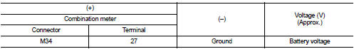
Is the inspection result normal? YES >> GO TO 2.
NO-1 >> Check 10 A fuse [No. 11, located in the fuse block (J/B)].
NO-2 >> Check harness for open or short between combination meter and fuse.
2.CHECK SECURITY INDICATOR LAMP SIGNAL
1. Connect combination meter connector.
2. Disconnect BCM connector.
3. Check voltage between BCM harness connector and ground.
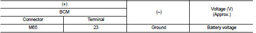
Is the inspection result normal? YES >> Replace BCM. Refer to BCS-161, "Removal and Installation".
NO >> GO TO 3.
3.CHECK COMBINATION METER CIRCUIT
1. Disconnect combination meter connector.
2. Check continuity between combination meter harness connector and BCM harness connector.
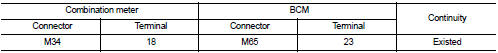
3. Check continuity between combination meter harness connector and ground.
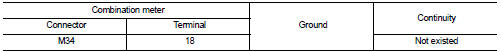
Is the inspection result normal? YES >> Replace combination meter. Refer to MWI-69, "Removal and Installation".
NO >> Repair or replace harness.
 Horn function
Component Function Check
1.CHECK FUNCTION 1
1. Disconnect vehicle security horn relay.
2. Perform ÔÇťVEHICLE SECURITY HORNÔÇŁ in ÔÇťACTIVE TESTÔÇŁ mode of ÔÇťTHEFT ALMÔÇŁ of ÔÇťBCMÔÇŁ
using CONSU ...

Other materials:
Precaution for Supplemental Restraint System (SRS) "AIR BAG" and "SEAT BELT
PRE-TENSIONER"
The Supplemental Restraint System such as ÔÇťAIR BAGÔÇŁ and ÔÇťSEAT BELT PRE-TENSIONERÔÇŁ,
used along
with a front seat belt, helps to reduce the risk or severity of injury to the
driver and front passenger for certain
types of collision. Information necessary to service the system safely is
...
Cargo cover (if so equipped)
WARNING
ÔÇó Never put anything on the cargo cover, no matter how small. Any object on
it could cause an injury in an accident or sudden stop.
ÔÇó Do not leave the cargo cover in the vehicle with it disengaged from the holder.
ÔÇó The child restraint top tether strap may be damaged by contact wi ...
B26F0 steering lock relay
DTC Logic
DTC DETECTION LOGIC
NOTE:
ÔÇó If DTC B26F0 is displayed with DTC U1000, first perform the trouble diagnosis
for DTC U1000. Refer to
BCS-83, "DTC Logic".
ÔÇó If DTC B26F0 is displayed with DTC U1010, first perform the trouble diagnosis
for DTC U1010. Refer to
BCS-84, &qu ...
