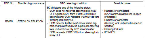
Nissan Juke Service and Repair Manual : B26F0 steering lock relay
DTC Logic
DTC DETECTION LOGIC
NOTE
:
• If DTC B26F0 is displayed with DTC U1000, first perform the trouble diagnosis
for DTC U1000. Refer to
BCS-83, "DTC Logic".
• If DTC B26F0 is displayed with DTC U1010, first perform the trouble diagnosis for DTC U1010. Refer to BCS-84, "DTC Logic".
DTC CONFIRMATION PROCEDURE
1.PERFORM DTC CONFIRMATION PROCEDURE
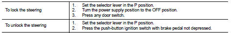
1. Press push-button ignition switch under the following conditions, and wait 2 seconds or more.
- Selector lever: In the P position.
- Brake pedal: Not depressed 2. Turn ignition switch OFF.
3. Press driver side door switch and wait 2 seconds or more.
4. Check DTC in “Self Diagnostic Result” mode of “BCM” using CONSULT-III.
Is DTC detected? YES >> Go to SEC-119, "Diagnosis Procedure".
NO >> INSPECTION END
Diagnosis Procedure
1.CHECK DTC OF IPDM E/R
Check DTC in “Self Diagnostic Result” mode of “IPDM E/R” using CONSULT-III.
Is DTC detected? YES >> Perform the diagnosis procedure related to the detected DTC. Refer to PCS-25, "DTC Index".
NO >> GO TO 2.
2.CHECK STEERING LOCK UNIT POWER SUPPLY
Check voltage between steering lock unit harness connector and ground.
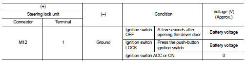
NOTE:
Is the inspection normal? YES >> GO TO 3.
NO >> GO TO 4.
3.REPLACE STEERING LOCK UNIT
1. Replace steering lock unit.
2. Perform the service procedure for steering lock unit replacement. Refer to CONSULT-III Operation Manual NATS-IVIS/NVIS.
>> INSPECTION END
4.CHECK STEERING LOCK RELAY CIRCUIT
1. Disconnect IPDM E/R connector and steering lock unit connector.
2. Check continuity between IPDM E/R harness connector and steering lock unit harness connector.
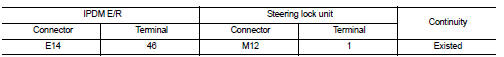
3. Check continuity between IPDM E/R harness connector and ground.
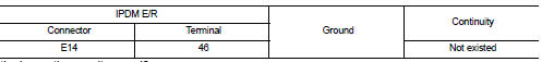
Is the inspection result normal? YES >> Replace IPDM E/R. Refer to PCS-34, "Removal and Installation".
NO >> Repair or replace harness.
 B26EF steering lock relay
DTC Logic
DTC DETECTION LOGIC
NOTE:
• If DTC B26EF is displayed with DTC U1000, first perform the trouble diagnosis
for DTC U1000. Refer to
BCS-83, "DTC Logic".
• If DTC B26EF is ...
 B26F3 starter control relay
DTC Logic
DTC DETECTION LOGIC
NOTE:
• If DTC B26F3 is displayed with DTC U1000, first perform the trouble diagnosis
for DTC U1000. Refer to
BCS-83, "DTC Logic".
• If DTC B26F3 is ...
Other materials:
Precaution
NOTE:
If any malfunction occurs in the RE0F10A model transaxle, replace the entire
transaxle assembly.
• Before connecting or disconnecting the TCM harness connector,
turn ignition switch OFF and disconnect negative battery
cable. Because battery voltage is applied to TCM even if ignition
s ...
Front seat belt
Exploded View
1. Adjuster cover
2. Anchor bolt
3. Shoulder anchor
4. Spacer
5. Retaining washer
6. Seat belt adjuster
7. Seat belt pre-tensioner retractor
(Passenger side)
8. Outer anchor
9. Seat belt pre-tensioner retractor
(Driver side)
10. Seat belt buckle
11. Wave washer
&n ...
Lane Departure Warning (LDW)
WARNING
Failure to strictly follow the safety warnings and operational instructions for the proper use of the Lane Departure Warning (LDW) system could result in an undetected drift, loss of vehicle control, and subsequent serious injury or death.
This safet ...
