Nissan Juke Service and Repair Manual : B26F3 starter control relay
DTC Logic
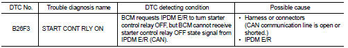
DTC DETECTION LOGIC
NOTE
:
тАв If DTC B26F3 is displayed with DTC U1000, first perform the trouble diagnosis
for DTC U1000. Refer to
BCS-83, "DTC Logic".
тАв If DTC B26F3 is displayed with DTC U1010, first perform the trouble diagnosis for DTC U1010. Refer to BCS-84, "DTC Logic".
DTC CONFIRMATION PROCEDURE
1.PERFORM DTC CONFIRMATION PROCEDURE
1. Press push-button ignition switch under the following conditions to start engine.
- Selector lever: In the P position - Brake pedal: Depressed 2. Wait 2 seconds after engine started.
3. Check DTC in тАЬSelf Diagnostic ResultтАЭ mode of тАЬBCMтАЭ using CONSULT-III.
Is DTC detected? YES >> Go to SEC-121, "Diagnosis Procedure".
NO >> INSPECTION END
Diagnosis Procedure
1.CHECK DTC OF IPDM E/R
Check DTC in тАЬSelf Diagnostic ResultтАЭ mode of тАЬIPDM E/RтАЭ using CONSULT-III.
Is DTC detected? YES >> Perform the diagnosis procedure related to the detected DTC. Refer to PCS-25, "DTC Index".
NO >> GO TO 2.
2.CHECK INTERMITTENT INCIDENT
Refer to GI-42, "Intermittent Incident".
>> INSPECTION END
 B26F0 steering lock relay
DTC Logic
DTC DETECTION LOGIC
NOTE:
тАв If DTC B26F0 is displayed with DTC U1000, first perform the trouble diagnosis
for DTC U1000. Refer to
BCS-83, "DTC Logic".
тАв If DTC B26F0 is ...
 B26F4 starter control relay
DTC Logic
DTC DETECTION LOGIC
NOTE:
тАв If DTC B26F4 is displayed with DTC U1000, first perform the trouble diagnosis
for DTC U1000. Refer to
BCS-83, "DTC Logic".
тАв If DTC B26F4 is ...
Other materials:
Engine oil
Inspection
ENGINE OIL LEVEL
NOTE:
Before starting engine, put vehicle horizontally and check the engine oil level.
If engine is already started, stop
it and allow 10 minutes before checking.
1. Pull out oil level gauge and wipe it clean.
2. Insert oil level gauge and check that the engine ...
LAN System can system (type 8)
DTC/CIRCUIT DIAGNOSIS
Main line between IPDM-E and DLC circuit
Diagnosis Procedure
1.CHECK CONNECTOR
1. Turn the ignition switch OFF.
2. Disconnect the battery cable from the negative terminal.
3. Check the following terminals and connectors for damage, bend and loose
connection (connector s ...
AWD warning light
The AWD warning light located in the instrument panel illuminates when the ignition
switch is turned to the ON position. It turns off soon after the engine is started.
If any malfunction occurs in the AWD system while the engine is running, or while
driving, the warning light will either rema ...
