Nissan Juke Service and Repair Manual : Differential side oil seal
Exploded View
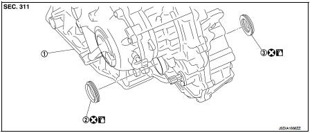 1. Transaxle assembly
2. Differential side oil seal (left side)
3. Differential side oil seal (right side)
 : Vehicle front
 : Always replace after every
disassembly.
 : Genuine NISSAN CVT Fluid NS-2
Removal and Installation
REMOVAL
NOTE
:
Cap or plug openings to prevent fluid from spilling.
1. Remove the left and right front drive shafts. Refer to FAX-53, "Removal and Installation".
2. Use oil seal remover or a similar means and remove the differential side oil seal.
CAUTION:
When removing the differential side oil seal, be careful not to scratch the oil
seal mounting surfaces
of the transaxle case and converter housing.
INSTALLATION
Note the following, and install in the reverse order of removal.
CAUTION:
• Never reuse differential side oil seal.
• Apply Genuine NISSAN CVT Fluid NS-2 to the differential side oil seal lip and around the oil seal.
• When inserting the drive shaft, be sure to use a protector (SST: KV38107900). Refer to FAX-53, "Removal and Installation".
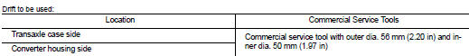
Use a drift (commercial service tool) and drive the differential side oil seal in until the amount of oil seal projection from the case edge matches dimensions (C) and (D).
CAUTION:
Be careful not to scratch the lip of the differential side oil seal
when press-fitting it.
A : Differential side oil seal (left side) B : Differential side oil seal (right side)
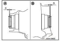
Dimension “C” :Height difference from case end surface is within 1.8 ± 0.5 mm (0.071 ± 0.020 in).
Dimension “D” :Height difference from case end surface is within 1.8 ± 0.5 mm (0.071 ± 0.020 in).
NOTE
:
The reference is the pull-in direction of the differential side oil seal.
Inspection and Adjustment
INSPECTION AFTER INSTALLATION
Check for CVT fluid leakage. Refer to TM-480, "Inspection".
ADJUSTMENT AFTER INSTALLATION
Adjust the CVT fluid level. Refer to TM-379, "Adjustment".
 Output speed sensor
Exploded View
1. Transaxle assembly
2. Output speed sensor
3. O-ring
: Vehicle front
: Always replace after every
disassembly.
: N·m (kg-m, in-lb)
: Genuine NISSAN CVT Fluid NS-2
Remova ...
 Water hose
Exploded View
1. Hose clamp
2. Water hose A
3. Water hose B
4. Water hose B
5. Water bypass pipe
6. Hose clamp
7. Heater hose
8. Water hose C
A. Water outlet
B. Heater thermostat
C ...
Other materials:
Intelligent key
Component Function Check
1.CHECK FUNCTION
1. Select “INTELLIGENT KEY” of “BCM” using CONSULT-III.
2. Select “RKE OPE COUN1” in “DATA MONITOR” mode.
3. Check that the function operates normally according to the following
conditions.
Is the inspection result normal?
YES >& ...
Air fresheners
Most air fresheners use a solvent that could affect the vehicle interior. If
you use an air freshener, take the following precautions:
• Hanging-type air fresheners can cause permanent discoloration when they contact
vehicle interior surfaces. Place the air freshener in a location that allows ...
B2267 engine speed
Description
The engine speed signal is transmitted from ECM to the combination meter via
CAN communication.
DTC Logic
DTC DETECTION LOGIC
Diagnosis Procedure
1.PERFORM SELF-DIAGNOSIS OF ECM
Perform “Self Diagnostic Result” of “ENGINE”, and repair or replace
malfunctioning parts.
...
